FIRST Tech Challenge Tech Tips
Started in the 2023-2024 season, Tech Tips are a weekly segment released in the FIRST Tech Challenge Team E-mail Blast. Sometimes the Tech Tips are included in whole in the email blast, but sometimes there is more content than is reasonable in the email blast so partial content is included in the blast with the rest of the content here. Blasts are ordered on this page chronologically, with the newest content at the top of the page.
Just click to expand the Tech Tip you’d like to read.
Week of 11/06/2024 “Android Studio 2024.2.1 LadyBug Update and the FTC SDK”
Android Studio 2024.2.1 LadyBug Update and the FTC SDK
This is an important message for teams who use Android Studio to program their robots. Teams who use Blocks or OnBot Java are not impacted.
On October 1, 2024 Android Studio released a new version of their software, 2024.2.1 codenamed “LadyBug”, which brought a major user interface change as well as several other changes (bundled software and tooling changes) that affects how Android Studio builds projects. Unfortunately these tooling changes broke the native compatibility with the FIRST Tech Challenge Software Development Kit (SDK), most notably with the FtcRobotController project. FIRST Tech Challenge teams who use Android Studio with software projects version 10.1 and older are not able to use Android Studio “LadyBug” without performing additional steps to restore compatibility.
Teams do not need to update Android Studio to “LadyBug” to continue building current software, however if they do, a new version of the FtcRobotController project (10.1.1) has been released which is designed to work with Android Studio “LadyBug.” Users will be required to upgrade their Android Studio software minimally to Android Studio 2024.2.1 “LadyBug” in order to use the 10.1.1 version of the SDK and newer. There are no feature updates to SDK 10.1.1, it is merely a compatibility update which updates the build tools used by the SDK - including the underlying Gradle tools and the Android Gradle plugin - and eliminates the need to perform any additional steps to use Android Studio “LadyBug” and newer. It is expected that future updates of the SDK will build upon this update, and will minimally require “LadyBug.” Teams who are using older versions of Android Studio who upgrade to SDK 10.1.1 will receive notifications within Android Studio to update the version of Android Studio, which may require an internet connection to update.
Teams are encouraged to read the Managing an Android Studio Project article on ftc-docs for tips on managing their projects using GitHub and the git version control system. Teams managing software projects outside of GitHub and git may re-download the project, reapply their changes, and copy over their TeamCode folder. Teams who need technical assistance may use the ftc-community forums to receive technical help and advice.
Week of 10/10/2024 “AprilTag Localization”
AprilTag Localization
This week’s Tech Tip is all about AprilTag Localization. How can your robot determine where it is on the field by looking at an AprilTag? A new set of APIs have been added to SDK 10.0 to provide just that information, and it works for any static (immobile) AprilTag on the competition field. Check out the AprilTag Localization documentation on ftc-docs!
Week of 09/09/2024 “AI Innovation Corner - Google AI Studio”
AI Innovation Corner - Google AI Studio
This week’s Tech Tip of the Week launches a new initiative in FIRST Tech Challenge, an AI Innovation Corner. Generative AI has taken the world by storm, becoming commonplace now in everything from personal assistants, search engines, recipe curation, music innovation, and vehicle maintenance! Machine Learning AI has been a part of FIRST Tech Challenge in some way for the past six years, and we’re now transitioning to help teams learn how to use and incorporate Generative AI in their FIRST Tech Challenge experience (while we’re learning ourselves!).
The first step (or FIRST step?) to getting the most out of AI is choosing a model. What do I mean by model? Every AI is a neural network that has been trained with specific knowledge with the ability to do specific things based on that knowledge. Each version of this neural network is stored in a “model”. Each different company has different models available for different purposes, though most models are variations on their flagship model (Gemini from Google, ChatGPT 4-o from OpenAI, Claude from Anthropic, and so on). Each company has different web-based and API interfaces for interacting with their models, and everyone has their favorite. In FIRST Tech Challenge, the standard tool we use is Google AI Studio to interact with Gemini.
Google AI Studio is free to use, but requires a Google account to access - virtually all models require a login or API token of some kind to use. Google AI Studio is our favorite for its list of examples (Prompt Gallery) and its easy to use interface to save prompt sessions and resume them later. With Google AI Studio, you also can select the specific model you want to use, and when available you can choose to use preview versions of up and coming models.
Future AI articles will be released not under the “Tech Tip of the Week” headline but under the “AI Innovation Corner” headline. Keep an eye out for future AI tips via the Team Blast and ftc-docs website!
Week of 08/19/2024 “REV Driver Hub Batteries”
REV Driver Hub Batteries
This week’s Tech Tip of the Week focuses on the REV Driver Hub. Sure, we already did a pretty thorough deep dive on the REV Driver Hub in the 11/06/2023 Tech Tip “Driver Hub or Smartphone?”, but we never really covered the batteries used in the Driver Hub themselves - and, of course, this topic was recently brought up in a team question. The question was, “Why aren’t batteries for the REV Driver Hub interchangeable?”
Well, that wasn’t the actual question, as the team didn’t know the question they SHOULD have been asking, but that was the root of the issue. The team in question had purchased an extra REV Driver Hub battery, charged it, and was using it as a spare. We’ve also heard anecdotes from teams who attended events where FTAs would also purchase spare batteries (or pull batteries from spare Driver Hubs) and let teams with depleted batteries use their charged batteries. However, in each case the teams noted that the spare battery never lasted as long as their “regular” batteries, often significantly shorter (half or less). The issue is actually not specific to the REV Driver Hub, but in the batteries themselves.
I noticed the same thing a few years ago when I owned a smartphone that had user-replaceable batteries. My phone battery stopped holding a charge, so I bought a battery online to replace it. However, I noticed that the replacement battery had a significantly lower “lifespan”, meaning it would go from full charge to near-dead in a shorter period of time versus the original battery. Over time the battery seemed to “last longer”, until after about a dozen charge cycles it was very close to the original battery’s performance. Did the battery get better, or did my phone adapt to the battery?
What I didn’t know was that minor variances in how batteries are manufactured, especially in lower-voltage Li-Ion batteries, can affect the voltage stability of the battery as it depletes (how the voltage of a battery changes as it’s used). In order to know how much battery power is left, the device needs to know the “charged” voltage, the “depleted” voltage, and generally needs to understand how the battery voltage changes from one extreme to the other. Unfortunately this isn’t linear, and differences in a battery’s specific internal resistance and other factors will cause each battery to have different behavior (this occurs in all batteries, but higher capacity batteries with low internal resistance tend to show this difference less). The REV Driver Hub performs a calibration phase as it charges a battery, and stores the battery charge characteristics - that helps it know how the battery should behave when it’s being depleted. In this way the Driver Hub “learns” how to interpret the battery it’s charging so that it can create an accurate charge profile for the battery as it’s used by the device.
When a team replaces the primary battery with a spare, the Driver Hub doesn’t necessarily know that this has happened, and can only apply the stored discharge characteristics for the primary battery to the new battery. Unfortunately this often leads to the device misinterpreting the battery and shutting down before the battery has fully depleted, or thinking there’s more battery left when there really isn’t. If the new battery is then charged, the Driver Hub will calibrate to the new battery, and changing the battery again will cause the Driver Hub to mischaracterize the original battery if replaced.
It is highly recommended that all teams use an external USB Battery Pack connected to the USB-C port on the Driver Hub to provide consistent power (use USB-A to USB-C cables only). The battery pack will sustain your Driver Hub and keep it from being additionally depleted by any high-power-drain gamepads (such as the Sony DualShock and Sony DualSense gamepads) that your team may be using.
Week of 07/29/2024 “Servo Power Injectors”
This week’s Tech Tip of the Week is intended to be a short treatise on Servo Power Injectors. Servo Power Injectors have been used in FIRST Tech Challenge for several years now, but do you really understand what they are and how they work? What is a Servo Power Injector and how might servos behave differently when used with one?
A servo connection is a 3-wire combination that combines power, ground, and a signal. The actual command signal for the servo travels on the signal wire, and the power used to power the servo travels on the other two wires. A servo power injector is a device that removes the power provided by the servo controller (REV Control Hub or REV Expansion Hub for FTC) and provides a new, usually higher wattage power source. Both the REV Servo Power Module and Studica Servo Power Block replace the 5V/10W power provided by the REV Control/Expansion Hubs with a 6V power source with a higher maximum wattage.
So what does higher voltage do for a servo? Servos operate on a power range; the more power they get, the faster and stronger they can become, up to a certain limit. Servos operating at 5V get a noticeable boost in speed and output power when used at 6V. The same servos may seem superhuman at higher voltages!
The downside of servo power injectors is that teams are now responsible for managing their own power usage. On the REV Control Hub, for instance, each servo port pair is limited in how much power it can draw (at least there’s a limit on how long it can draw high loads). When using a servo power injector, the pool of power for a servo is much larger and less restricted since it pulls its power directly from the robot battery - using power injectors means you could consume all of the power on the robot just from the servos alone! This will result in the robot power system browning out (resulting in loss of communications or loss of power to the control system) or even blowing the 20A battery fuse.
Using a servo power injector can also expose different behaviors in servos that were not present when using the REV Control/Expansion Hub directly. The biggest behavior is the “Lost Signal” behavior. When an OpMode ends, the REV Control/Expansion hubs stop the signal and also cut power to the servo ports - this leads to the servos “going limp” as they lose power. With a servo power injector, the servos never lose power, and so “lost signal” behaviors will often then take over which may cause the servo to move to a “default” position (which is virtually never advantageous for robots but definitely advantageous for R/C planes for example). The Axon MAX+ servo and several higher-power HiTec servos have this behavior, the Axon MAX+ behavior is at least configurable with a servo programmer.
Finally, when using a servo power injector it’s of VITAL importance that you cover unused ports with tape or other debris-limiting measures to protect the ports. It’s very easy to get metal swarf in open servo ports, and that metal can short out the power output pins - especially lower-cost power injectors cannot tell when they’re being used, or don’t have protections against short circuits, but they still have all output pins powered. This can quickly turn your servo power injector into an expensive paperweight when the power regulator overloads and burns out.
Week of 06/24/2024 “Calculating Motor and Servo Power”
In this Tech Tip of the Week we’ll be exploring mechanical and electrical power, why some types of power are calculated differently, and how to use this calculated power to compare servos. This Tech Tip was written and fact-checked with the help of Google Gemini 1.5 Flash using Google AI Studio.
The fundamental concept we need to understand is power. We are generally concerned with two similar but different kinds of power, so let’s look at the two most common types. In a motor, electrical power is the energy supplied by the electrical current flowing through the motor’s windings. This electrical energy is transformed into mechanical power, which is the rate at which the motor performs work by rotating a shaft. Both kinds of power are measuring different aspects of the motor; electrical power deals with the movement of electrical charges, and mechanical power deals with the movement of objects due to forces. Both of these measurements are expressed in the same unit, Watts (W), because power, in general, is defined as the rate of energy transfer or work done. No matter the form of energy (electrical, mechanical, thermal, etc.) the fundamental concept of power remains the same. Even though these two power measurements carry the same unit, they are calculated differently and cannot be used interchangeably (or together!).
Motors and servos are constructed similarly - both are electromechanical devices that convert electrical energy into mechanical energy - but there are big differences in how they’re used. Motors are often used in applications requiring continuous power, such as pumps, fans, and conveyor systems. Motors are typically rated for continuous power output, meaning they can sustain that power level indefinitely without overheating. Servos are commonly used in robotics and precision positioning systems, where controlled movement and precise positioning are essential. Servos are designed for intermittent operation - typically cycling through on/off periods to control movement - and are often rated for their stall torque and no-load speed reflecting their ability to hold a position against a force and how fast they move when unloaded. While electrical power is calculated generally the same for both types of devices, these design and use differences have an impact on how mechanical power is determined.
Both motors and servos calculate electrical power the same, using the standard electrical power formula:
Electrical Power(W) = volts(V) x amps(A)
For example, a typical REV Smart Servo is supplied with 6V when used with a REV Servo Power Module (SPM) or 5V when used with a Control or Expansion Hub. Per the servo’s specs, at 6V the servo will pull at most 2A at stall (when the servo cannot physically move to the position it’s being commanded to). This means the maximum electrical power the servo will consume is 12Watts of power when plugged into the REV SPM and being commanded to a position it cannot reach. The REV SPM supplies 90W of maximum electrical power, so the maximum number of fully-stalled REV Smart Servos the SPM can supply full power to is 7 (90W divided by 12W, ignoring the remainder).
Motors and servos also generally calculate mechanical power similarly.
Mechanical Power(W) = torque (N-m) x angular speed (rad/s)
Mechanical Power for a DC motor generally follows a very specific curve, based on its efficiency, stall current, stall torque, speed, and a bunch of other factors. The general performance curve of a DC motor can be seen in Figure 1.
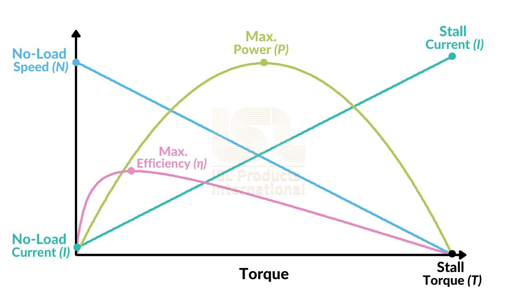
Figure 1: General DC Motor Performance Curve
From this we can see that the Peak Power is found at the intersection of 1/2 Stall Torque and 1/2 Speed. Even though a servo is used different than a generic motor, this approximation is still good for calculating the maximum mechanical power of a servo. Simplified, we can use this formula:
Servo Max Mechanical Power(W) = 0.25 x stall torque(N-m) x no-load speed(rad/s)
Using this approximation the REV Smart Servo, when being provided 6V, produces a maximum Stall Torque of 13.5kg-cm (1.33N-m) and a time of 0.14s per 60 degrees of travel (7.48rad/s) yielding an approximate max servo mechanical power of 2.48W.
Tip
It’s important to point out that a high speed motor or servo that is loaded past its maximum power point will actually do worse than a slower motor or servo with the same load. It’s all about getting the maximum mechanical power by operating the motor at the max power point.
One of the most difficult parts of calculating Servo Mechanical Power is working with unit conversions, especially since servo manufacturers use lots of different units. In order to calculate servo mechanical power correctly the speed unit MUST be converted to radians-per-second and the max stall torque unit MUST be converted to Newton-meters. Below is a handy calculator that you can use to automatically perform the necessary conversions and calculate Servo Mechanical Power (Thank you to Orion DeYoe for providing this tool).
Tip
For Speed, use the radio button to choose the unit type that the manufacturer has provided - for most servos this will be listed in a period of time per 60 degrees (such as with the REV Smart Servo example) or perhaps the manufacturer may provide an angular velocity, such as rotations-per-minute (RPM). Enter the no-load speed value and unit as the manufacturer has provided.
For stall torque, provide the value and select the unit as specified by the manufacturer. If the manufacturer merely provides kg, assume kg*cm.
The calculator automatically recalculates on any changes, there is no button to press in order to trigger a calculation.
Here is a handy table of some common servo mechanical power values:
Description |
Speed |
Torque |
Stall Current |
Max Power |
Cost ($USD) |
|---|---|---|---|---|---|
0.18 s/60° |
6 kg-cm |
1.2 A |
0.86 W |
$29.50 |
|
0.14 s/60° |
13.5 kg-cm |
2.0 A |
2.48 W |
$30.00 |
|
0.09 s/60° |
9.3 kg-cm |
2.5 A |
2.65 W |
$33.99 |
|
0.075 s/60° |
7.8 kg-cm |
2.2 A |
2.67 W |
$63.79 |
|
0.20 s/60° |
300 oz-in |
2.5 A |
2.77 W |
$33.99 |
|
0.046 s/60° |
5 kg-cm |
2.7 A |
2.79 W |
$24.99 |
|
0.043 s/60° |
4.7 kg-cm |
2.5 A |
2.81 W |
$33.99 |
|
0.20 s/60° |
22 kg-cm |
1.7 A |
2.82 W |
$34.00 |
|
62 RPM |
20 kg-cm |
1.8 A |
3.18 W |
$23.99 |
|
0.05 s/60° |
7 kg-cm |
2.7 A |
3.59 W |
$30.00 |
|
0.20 s/60° |
35 kg-cm |
4.0 A |
4.49 W |
$52.95 |
|
0.14 s/60° |
24.7 kg-cm |
6.0 A |
4.53 W |
$49.99 |
|
0.17 s/60° |
34 kg-cm |
2.7 A |
5.13 W |
$199.99 |
|
0.083 s/60° |
20 kg-cm |
4.0 A |
6.19 W |
$120.00 |
|
0.09 s/60° |
25 kg-cm |
3.8 A |
7.13 W |
$79.99 |
|
0.115 s/60° |
34 kg-cm |
4.0 A |
7.59 W |
$79.99 |
Week of 06/10/2024 “Updating the SDK Manifest”
This week’s Tech Tip of the Week comes to us from an amalgamation of emailed questions asking about allowed ways to update an FtcRobotController SDK project. An approximate summary of the emailed questions along this topic is as follows:
“Is merely editing the Android Manifest file in the TeamCode directory of the FtcRobotController SDK project an acceptable way of easily updating the SDK? And would this violate RS08 in Game Manual Part 1?”
Manually editing the Android Manifest file in the TeamCode Directory of the FtcRobotController SDK software is not a violation of RS08, merely because RS08(b) only protects the binary .AAR files. The manifest file is not part of the .AAR binary, and thus it’s not protected.
Even though it’s not forbidden, that doesn’t mean you should do it – like putting pineapple on pizza (sorry, the door was open, I couldn’t stop myself). Seriously, though, 4 times out of 5 you can likely get away with updating the SDK through editing the Android Manifest to point to the latest version of the SDK libraries. However, that assumes that all the Tech Team does is update the SDK libraries, which is never ever the case. In addition to also updating programming samples, often enough the Tech Team must also update tooling, dependencies, and other build items in addition to the SDK libraries, and simply updating the Android Manifest is going to get you into real trouble (things will appear to work, until they don’t, and you won’t know why). As a corollary, you can choose to simply only put gas in your car and ignore all the other fluids, but eventually you’re going to wish you hadn’t.
The proper way of updating your SDK is to use Git/GitHub to update your robot source each time the SDK software updates. The Tech Team always updates the FtcRobotController in-place (meaning the same repo is always updated each version), so if you’re using Git you can easily pull the changes made upstream and accept the changes within your code. You should never be manually updating files, like the Android Manifest file, because Git can tell you all of the files you need to update and can do that for you. If you use Git or GitHub, we highly recommend reading our guide on ftc-docs for managing your Android Studio project repositories.
For example, check out these changelists. The FtcRobotController v9.0 commit/change is everything that needs to be changed to upgrade from version 8.2 to 9.0 – there are 75 changed files there, which include samples, a core interface module change, gradle dependencies, and in that changelist the Tech Team also rearchitected the asset structure. However, the FtcRobotController v9.0.1 and FtcRobotController v9.1 pull requests only changed a handful of files (mostly samples), and the core changes are in the AndroidManifest.xml and build.dependencies.gradle files. In general our major version releases (where we increase the first number in the version string) are the big ones, and then the dot-releases are almost always fairly small targeted releases. The Tech Team tries very hard not to make big-scale changes to build systems or major dependencies during the season.
In summary, teams should never simply change the Android Manifest, they should be updating the software appropriately – as Voltaire warned, with great “Android Studio” power comes great “GitHub” responsibility.
Week of 05/20/2024 “Wi-Fi Bands, Part 3”
Welcome back to the Tech Tip of the Week, this is Part 3 of a 3-part series talking about Wi-Fi bands and why you might be shooting yourself in the foot by not selecting (and designing your robots for) the right Wi-Fi band. In Part 1 we discussed the physical characteristics and properties of frequencies in each of the 2.4GHz and 5GHz bands. In part 2 we talked about the history of the bands, described sources of interference (e.g. other devices!) on each band, and how Wi-Fi improvements have made 5GHz more efficient to use.
Robot design - and more aptly “Control Hub placement” - is THE critical factor in influencing the Wi-Fi frequency/band you should be using. Remember Wi-Fi is a line-of-sight technology, that means Wi-Fi does best when there’s a straight unobstructed path from the antenna on the Control Hub to the antenna on the Driver Hub. Where is the antenna in a Control Hub? It’s right under the plastic on the “face” of the hub on the logo side. If the Control Hub can be mounted so that its antenna is generally not covered/surrounded/blocked by metal, 5GHz should be your target band. However, if your Control Hub is buried deep inside the robot and surrounded by metal, the 2.4GHz band may be your only option (remember, the lower frequencies of 2.4GHz might be able to “bend around” metal obstacles slightly better). Unfortunately exposing the “back side” of the Control Hub instead of the “front side” of the hub is not going to yield similar results, as there is a PCB with metal traces between the antenna and the “back side” of the Hub that will block/reflect/absorb signals.
Does that mean your Control Hub needs to be mounted unprotected on the outside of the robot in order to get good signal reception? Not necessarily, fortunately not all materials are the same. Plastics are generally the most “invisible” to Wi-Fi frequencies, or at least their absorption/blocking/reflection (also known as attenuation) is generally minimal enough to not sufficiently matter. Wood, especially thin birch commonly used in many robot designs, is slightly more attenuating but definitely still a great option. Metals, however, will greatly attenuate Wi-Fi frequencies and are the worst materials for Wi-Fi transmission. Yes, I’m looking at YOU teams who use hook-and-loop to mount your robot battery to the top of the Control Hub - stop doing that! And for those looking for inspiration in this upcoming season, water is also an incredibly poor medium for transmission of Wi-Fi frequencies.
But how do you know for sure how well your robot’s Wi-Fi is performing? You can monitor the Wi-Fi signal’s strength through the Driver Station App. Check out the 2024/02/15 Team Blast Tech Tip for info on how to view and understand Wi-Fi Signal Strength. If your signal is strong when using 5GHz at maximum field range (from the Driver Hub) and in all robot orientations, you should be good to go on 5GHz! Feel free to compare the performance on 5GHz and 2.4GHz, and if they’re comparable you should stick with 5GHz for better interference reduction.
In summary, the vast majority of robots should be using 5GHz as this is the optimal channel in terms of interference reduction, device crowding, and channel utilization by the Wi-Fi standards. Robot design - specifically Control Hub placement - might necessitate the use of 2.4GHz if the line-of-sight path to the Control Hub antenna in the robot is too greatly obstructed by metal, especially motors. By monitoring the robot’s Wi-Fi signal strength, you can determine which frequency band yields the best Wi-Fi signal performance for your robot.
Week of 05/06/2024 “Wi-Fi Bands, Part 2”
Welcome back to the Tech Tip of the Week, this is Part 2 of a 3-part series talking about Wi-Fi bands and why you might be shooting yourself in the foot by not selecting (and designing your robots for) the right Wi-Fi band. In Part 1 we discussed the physical characteristics and properties of frequencies in each of the 2.4GHz and 5GHz bands. In this part we’ll talk about sources of interference.
You might have realized this, but wireless devices are all the rage. The FCC (in the USA) doesn’t just let any device broadcast on any frequency they want. Instead, there are licensed and unlicensed radio frequency bands. Some frequencies are uniquely licensed to private operators, for example radio stations pay a lot of money to the FCC for the exclusive rights to broadcast on specific frequencies. HAM radio operators undergo special training to be allowed to broadcast on a range of licensed frequencies (some reserved only for HAM radio, some not). The FCC also sets aside frequencies that are unlicensed, meaning the operators themselves (like you, your neighbor, or the kid down the street) don’t need training or licensing to operate devices that broadcast on those frequencies. The devices themselves must adhere to specific regulations, but those requirements are generally easy to meet.
Wi-Fi uses portions of the radio frequency spectrum designated as unlicensed - remember that these frequencies are available to the general public to use - so anyone can broadcast signals over it. And boy howdy do they. The 2.4GHz frequency band was opened to the public in 1985, and devices began using that frequency for use. Wi-Fi emerged in the late 1990’s. The 2.4GHz frequency band became extremely crowded, and by devices using different protocols - think about trying to have a conversation with a friend in a crowded room, but some people are talking “normally”, some are using air horns, and others are mimicking nails on a chalkboard. The resource was very narrow, but at least interference was just a matter of distance - though not everyone lives in the deserts of Arizona where they can carry out their conversations in relative peace.
By the turn of the 20th century, the 5GHz space was opened up for unlicensed use. This required different hardware, as the 2.4GHz devices couldn’t simply just start using 5GHz. The 5GHz band was much larger, and it took longer for it to become crowded as more devices came onto the market that could use it. 5GHz already had a bunch of legacy systems that used portions of it, and so the FCC grandfathered those systems and made special regulations for using those frequencies (most manufacturers designed their devices to only use the portions of the 5GHz band with the least rules and regulations). Some uses of 2.4GHz could not move to 5GHz because of the frequency wave propagation behaviors (that we talked about previously, e.g. reflections and wave bending), but many systems like Wi-Fi found the greatest use in 5GHz. The number of channels and the frequency space was much larger in 5GHz, and 5GHz Wi-Fi technologies learned to use the 5GHz space more efficiently and robustly.
When you consider which frequency you should use, you have to consider many factors. How obstructed is the path from the radio to the receiver? How crowded might the frequency space be that you’re trying to use? Has the event organizer worked with the venue to clear specific channels for robots to use? What advanced technologies might the device you’re using be capable of utilizing on specific frequency bands?
In Part 3 of this series we’ll talk about how robot design can influence the Wi-Fi frequency you should be using, how to design for the best possible outcome, and how to characterize your optimal band.
Week of 04/29/2024 “Wi-Fi Bands, Part 1”
Welcome to the Tech Tip of the Week, where this week hopefully “Bandwidth of Robots” will be your new favorite way to refer to groups of wireless robots. Today we’ll be starting a three-part series talking about Wi-Fi bands and why you might be shooting yourself in the foot by not selecting (and designing your robots for) the right Wi-Fi band. And at the end of the day how do you truly know which band you should be using?
If you’re anything like the average team, Wi-Fi bands are something nebulous that you don’t really understand or even give a second thought to. At least, until “bad things” start happening and you’re grasping at straws trying to resolve them. So let’s start this discussion by talking about radio frequency bands and then the two Wi-Fi bands we have access to, 2.4GHz and 5GHz.
What are the important properties of Wi-Fi frequencies we should know? To explain Wi-Fi frequencies, let’s look at something most of us might already be more familiar with - AM and FM radio frequency bands (which share similar behaviors, ignoring modulation differences).
AM radio stations are assigned carrier radio frequencies between 540kHz-1600kHz. For example WGHM 900 AM out of Nashua, NH, is licensed to broadcast at 900kHz. AM radio station signals travel very far very easily mostly because the frequencies in AM radio have very large wavelengths - 900kHz, for example, has a full wavelength of 333m (just over one fifth of a mile) - and because of this they can bend around obstacles very easily (buildings, mountains, curvature of the earth, etc). However, long wavelength AM radio is more susceptible to interference and static than shorter wavelength transmissions, like FM.
FM radio stations are assigned frequencies between 88.1MHz-108.1MHz. For example, WEVS 88.3 FM also in Nashua, NH broadcasts at 88.3MHz. FM radio frequencies are higher frequency, and have a shorter wavelength - 88.3MHz is about 3.4m (about 11 feet) in wavelength - and cannot bend around obstacles as easily. Shorter wavelength frequencies also tend to be absorbed/reflected (comparatively) much easier by obstacles as well.
Hence when driving through the mountains and forests of NH I am more apt to be able to cleanly listen to the AM station uninterrupted but not the FM station, even though they’re broadcasting at roughly the same power and from very similar locations.
Frequency bands used for Wi-Fi share very similar characteristics, but because the frequencies for Wi-Fi are much higher some characteristics are more exaggerated. As an analogy, for the purposes of this discussion, we can say that 2.4GHz is to 5GHz as AM is to FM. 2.4GHz frequencies have a longer wavelength (starting at ~0.125m or ~5 inches) than 5GHz frequencies (starting at ~0.05m or ~2 inches), and because of that 2.4GHz radio waves can bend around objects better than 5GHz ones but are much more susceptible to interference than 5GHz. Similarly 5GHz frequencies will also tend to be reflected/absorbed much easier by solid objects, and so 5GHz tends to perform better with an unobstructed line of sight between antennas.
In Part 2 of this series we’ll talk more about the challenges Wi-Fi faces because unlike AM and FM radio, Wi-Fi doesn’t have dedicated frequency space. This can cause legitimate issues due to the number of existing devices and services that already use frequencies that Wi-Fi has to share.
In Part 3 of this series we’ll talk about how robot design can influence the Wi-Fi frequency you should be using, how to design for the best possible outcome, and how to characterize your optimal band.
Week of 04/08/2024 “What makes Battery Voltage Sag? Part 3”
This Tech Tip of the Week is Part 3 in a 3-part series surrounding a question that we get asked at events all the time - “What makes battery voltage sag?”. As a battery is heavily used, teams will notice that the voltage of the battery temporarily decreases from its starting voltage during periods of heavy use, and then generally raises back up once the heavy use has subsided. So what causes this?
There are LOTS of reasons why battery voltage will sag during use. In Part 1 we talked about battery chemistry to give an idea how a battery works, and we talked about how motor torque is inversely proportional to the power consumption (given a constant load). Part 2 covered cell health and battery temperature, both of which can affect a battery’s performance and longevity. This week, we’ll cover another major factor which is Internal Resistance (IR).
Understanding IR requires talking about the discharge rate of a battery. The discharge rate is a measure of how quickly the battery can deliver its stored energy. Most NiMH batteries used in FIRST Tech Challenge are rated at a nominal 12V and a maximum discharge rate of 30A, though that rate is limited by the 20A fuse. A battery’s IR refers to any opposition to that flow of electric current within the battery itself. Resistance can come from a number of sources, such as resistance within the battery’s chemistry (such as a breakdown of the conductive electrolyte within the battery), changes to the resistance of the electrodes (such as a buildup of crystals around the electrodes), resistance added due to connectors and wiring, and others. Rising IR affects the battery performance primarily in decreasing the Voltage and Current that the battery can provide, and causes the battery to generate excess heat when used. The starting IR of a battery can vary among different manufacturing processes and batches, so much that batteries should have their IR measured (using a CTR Battery Beak, West Mountain Radio CBA, or similarly capable battery tester - YOU CANNOT MEASURE INTERNAL RESISTANCE DIRECTLY WITH A MULTIMETER, ATTEMPTING TO DO SO WILL BLOW YOUR FUSE AND MAY DAMAGE THE MULTIMETER!) at “birth” (when “new” at time of purchase) and the IR then should be tracked over time. Once the battery’s IR increases by 50% from when it was “born”, the battery is universally considered ready for replacement.
Danger
You cannot measure the internal resistance of a battery directly with a multimeter. Please do not even try. Doing so will certainly blow your multimeter’s fuse, and may even damage the multimeter. Please do not attempt. Internal resistance can only be measured indirectly using a load-measuring device like a CTR Battery Beak.
What can teams do to slow the increase in a battery’s IR? Naturally the battery’s IR will change as the battery ages, increasing due to chemical changes and wear and tear. The temperature of the battery can also have a negative effect on IR, higher temperatures cause higher resistance (so keep your batteries cool!). It’s also important to note that the state of charge of a battery can change the IR, battery IR should always be measured fully charged. But the most important ways to keep your battery healthy are to avoid deep discharges (avoid letting your batteries drain below 10V steady-state, definitely never below 9V!), use a high-quality charger that prevents batteries from overcharging, follow the battery manufacturer’s recommended charging procedures, and use low-resistance connections (thick wires and clean connectors!).
Finally, the IR of NiMH batteries can also sometimes be decreased through a process known as “battery conditioning” (also referred to as “charge cycling”). If IR within a battery is raised due to crystal formations inside the battery, this process of conditioning can help break down those crystal formations and improve Voltage and the flow of current in a battery. Some chargers have automatic conditioning modes, but always refer to your manufacturer’s recommended procedure for charge cycling your NiMH batteries.
Week of 04/01/2024 “What makes Battery Voltage Sag? Part 2”
This Tech Tip of the Week is Part 2 in a 3-part series surrounding a question that we get asked at events all the time - “What makes battery voltage sag?”. As a battery is heavily used, teams will notice that the voltage of the battery temporarily decreases from its starting voltage during periods of heavy use, and then generally raises back up once the heavy use has subsided. So what causes this?
There are LOTS of reasons why battery voltage will sag during use. In last week’s Tech Tip we talked about battery chemistry to give an idea how a battery works, and we talked about how motor torque is inversely proportional to the power consumption (given a constant load). In this week’s Tech Tip we’ll cover two more common reasons - cell health and battery temperature. In subsequent Tech Tips we’ll cover other reasons, such as the internal resistance of the battery.
Battery cell health is an important factor in the overall health of a battery. An NiMH battery used in FIRST Tech Challenge is a multi-cell battery, meaning it’s composed of individual smaller batteries connected together. Each cell contributes to the overall power output of the battery. As a battery ages, individual cells in the battery may age at different rates - this aging can lead to degradation of cell material, electrolyte breakdown, and creation of dendrites that can eventually puncture the cell wall from inside the cell among others. Most often this cell breakdown is accelerated due to improper storage, overcharging, deep discharging, excessive temperatures, or physical damage (especially due to dropping). When a cell fails, it can lead to a reduced capacity of the battery pack, and the battery will not last as long on a single charge nor will it be able to provide the peak power output that it previously could. Failed cells can cause other cells to fail prematurely, primarily due to overcharging and imbalanced voltage due to the fact that NiMH batteries and chargers for NiMH batteries do not contain a load-balancing management system for individual cells. In some cases, failed cells can cause short circuits, overheating, and increased risk of fire/explosion! If you’re suspicious of a battery, get it tested before using it again.
Battery temperature is also an important consideration. When a battery is being charged, it will likely become warm and even slightly hot to the touch - this is expected and natural due to the process of recharging a battery. NiMH batteries deliver their best performance at moderate temperatures. When a battery is hot from charging, its internal resistance increases (we’ll cover internal resistance in a future segment) which can lead to reduced power output. Allowing the battery to cool down before use helps to ensure optimal performance. This process of allowing the battery to cool down before use can also prolong the life of the battery. This advice should also be tempered with the knowledge that most modern NiMH batteries are generally designed to handle some degree of heat; if you need to use the battery immediately after charging, it’s usually safe to do so as long as the battery is not excessively hot to the touch. However, understand that it may not provide the maximum level of power output as it would have if it had cooled first.
Week of 03/25/2024 “What makes Battery Voltage Sag? Part 1”
This Tech Tip of the Week is a short one, Part 1 in a 3-part series surrounding a question that we get asked at events all the time - “What makes battery voltage sag?”. As a battery is heavily used, teams will notice that the voltage of the battery temporarily decreases from its starting voltage during periods of heavy use, and then generally raises back up once the heavy use has subsided. So what causes this?
There are LOTS of reasons why battery voltage will sag during use. In this week’s Tech Tip we’ll cover the most common two reasons - battery chemistry and heavy use. In subsequent Tech Tips, we’ll cover other reasons, such as battery cell health, battery temperature, internal resistance, and other factors to be aware of!
The first thing to remember is that a battery is a chemical reaction factory, and does not exactly work the same as the typical “gas tank” analogy makes it seem. The chemical reactions at the electrodes create a potential difference (voltage) between them. This voltage drives the flow of electrons generated by hydrogen and hydroxide ion creation and transfer. In NiMH batteries this reaction is reversible but it takes time and energy. What’s important to understand is that the chemical reaction can happen only at a specific rate (the rate is based on a number of factors which we’ll discuss later); if the demand exceeds the rate of reaction for the battery, the voltage and current will drop until the reactions can replenish the battery output (this temporary drop is known as “sag”). As the materials at the electrodes are gradually consumed, the overall battery charge will deplete and can no longer sustain the flow of electrons, and the battery will need to be recharged or replaced.
So what is the biggest reason why batteries will sag? On a FIRST Tech Challenge robot, this reason is actuator (motor and servo) current draw. Motors and Servos can pull a considerable amount of current when they’re being used, especially when they’re being used in low-torque configurations. Motors that are geared closer to 1:1 gear ratio can spin faster - they can propel your robot’s drivetrain across the field much faster - but have less torque because of the lower gear ratio. Motor configurations that have less torque consume significantly more current to operate (when driving the same load) than motor configurations with more torque. Systems being driven by actuators that have more friction or less torque will cause the motors to consume larger amounts of current, and this can cause even healthy batteries to have their voltages “sag” during periods of high use. Teams must consider their power consumption very carefully when optimizing their battery and motor utilization during a match, even though that’s often an afterthought for most teams.
Week of 03/18/2024 “Battery Fuses”
Welcome to the Tech Tip of the Week, where hopefully after reading you don’t blow a fuse. Yup, you guessed it, we’re talking today about fuses - more specifically, we’re talking about the fuses on your Main Robot Battery.
Every legal Main Robot Battery in FIRST Tech Challenge is required to have an in-line replaceable fuse on the battery, you’ll find the fuse housing on the red (positive) cable on your battery between the battery and the connector (the top lifts off, exposing the fuse). This fuse helps protect your battery and your electronics from prolonged or excessive over-current. The fuse used with all legal batteries is a 20A Automotive-Mini (ATM) blade-style fuse, and can be found in virtually every auto parts store. It has a yellow-colored housing which easily identifies it as a 20A fuse. If you find that your battery’s voltage suddenly drops to zero (when tested using a battery tester or multimeter) it’s probably because you’ve blown your battery’s in-line fuse.
A fuse is a short span of specially-designed electrical wire intended to carry electrical loads up to a very specific amount of current. When the current loads exceed the rating, the wire within the fuse begins heating up - the more the load exceeds the rating, the hotter the wire will get. Eventually the wire will heat up so much it self-destructs and melts or burns up, breaking the circuit. This fuse-melting condition is often called “Blowing a Fuse”; the fuse is thus destroyed and is no longer usable, but it protected the electronics in the circuit as its last selfless act.
How does a fuse battery get blown? These are two of the most common reasons why a fuse can be blown:
Overcurrent Conditions - The Robot has components (generally actuators, like servos and motors) that can pull a combined current that is more than the robot’s electrical circuit can safely carry. The main electrical power wires on a robot are required to be a minimum 18AWG, which can easily continuously carry up to 16A of current. When components pull a combined current far exceeding this limit, generating unsafe heat in excess of what the wires can tolerate (risking melting the wire insulation which could lead to short circuits and fire), the fuse blows to protect the circuit. The wire size and fuse limit has been carefully selected for the safety of the robot’s electrical system. Short Circuits - Usually this happens if unshielded wires of opposite polarity touch each other in the robot’s electrical system, like when performing electrical maintenance on switches or wires (ALWAYS unplug the battery before performing any maintenance on a robot!). Other causes can be failed electronics and damaged components. This causes an extremely high current load to travel through the battery, near-instantly causing the fuse to blow. When replacing the connector on a battery, ALWAYS remove the fuse prior to performing any work - this protects the person doing the maintenance AND protects the fuse!
Always make sure your main battery fuse is replaced with the proper fuse (20A for FIRST Tech Challenge) and make sure you’re always following all safety guidelines when working with your robot’s electrical system!
Week of 03/11/2024 “Signal Filtering with Ferrite Cores”
For those about to use sensors, we salute you - with our Tech Tip of the Week! This week’s Tech Tip focuses on signal noise and how to eliminate it with ferrite cores.
When deciding to use a sensor on a robot, we’re normally worried about how accurate the sensor’s detection is, how much the sensor costs, or how the sensor’s protocol will interface with the control system. It isn’t until the device is being mounted to the robot before we consider how outside electrical noise already present on the robot might significantly impact the performance of the sensor. This electrical noise almost exclusively comes from the electric motors and other sources of electric fields on a robot, such as power wires, power supplies, some sensors (especially ultrasonic sensors and cameras), radio frequency generators (like the Wi-Fi on the robot), and other places. This electrical noise can generate unwanted currents through electromagnetic induction in nearby wires, especially sensor wires, and these unwanted currents can wreak havoc (create “noise”) within the signals from your sensors. The amount of current induced in the wire depends on several factors including the strength of the magnetic field, the rate of change of the field, and the orientation of the wire.
Some buses and wiring are more sensitive to electrical noise than others. On a FIRST Tech Challenge robot, long signal-carrying wires (such as Servo wires or I2C sensor wires) are most susceptible to induced noise. So how can we eliminate this noise? The easiest way to remove noise is through the use of a Ferrite Core. Ferrite Cores, also known as Ferrite Beads, are made of a ceramic material called ferrite that has incredibly useful magnetic properties. When a Ferrite Core is clipped around a signal-carrying wire, the induced “noisy” alternating currents in the wire generate electrical fields in the ferrite that act to oppose those currents - this has the effect of canceling out or removing the high-frequency noise. It’s not typically required to “loop” the cable around the ferrite core, but doing so could increase the efficiency of the noise filtering in cases where excessive noise is being generated. You can find ferrite cores already installed in cables meant for high-noise environments or highly sensitive devices such as USB webcam cables and monitor cables. It’s best to place ferrite cores on the wire closest to the connector leading into the Control/Expansion Hub port.
Week of 03/04/2024 “Motor Modes”
This week’s Tip of the Week is the first in a series for all you who love diving deep into the FIRST Tech Challenge SDK and exploring interesting lesser-known behaviors of well-known interfaces. Today we’re talking about motor modes. The REV Robotics documentation for encoder feedback has a really good description of the four primary run modes, namely:
DcMotor.RunMode.STOP_AND_RESET_ENCODER mode
DcMotor.RunMode.RUN_WITHOUT_ENCODER mode
DcMotor.RunMode.RUN_USING_ENCODER mode
DcMotor.RunMode.RUN_TO_POSITION mode
The first two modes do exactly as their names suggest, and generally no more. STOP_AND_RESET_ENCODER stops the motors and resets the encoder count to zero. RUN_WITHOUT_ENCODER more or less blindly controls the motor power using a calculated percentage of the available battery power through the motor’s .setPower() method. There’s really no more to see here.
The last two modes are a bit more interesting. These two modes use a feature of the Control/Expansion hub firmware to externally (from robot code) control the motors. Using this feature you can do a lot more with the motors such as set the maximum velocity of the motor (nominally in encoder-ticks-per-second) using the .setVelocity() method, and change the actual PIDF algorithm being used by the motor mode (using the .setPIDFCoefficients() methods). Because these two motor modes rely on knowing specific motor characteristics, it’s VERY important to set the correct motor type for the motor in the Robot Configuration!
Finally, one final note about RUN_TO_POSITION. When setting a Power or a Velocity for the motor in RUN_TO_POSITION mode, the value is intended to be unsigned. When using RUN_WITHOUT_ENCODER and RUN_USING_ENCODER the sign of the value of the Power or Velocity denotes direction; positive values mean run the motor “forwards” and negative values mean run the motor “backwards.” However, with RUN_TO_POSITION, the current encoder value and target encoder position are already known - and thanks to the motor setting in the Robot Configuration it knows everything about the motor - therefore the controller already knows which direction to run the motor and does not need a signed value indicating direction.
Week of 02/26/2024 “Robot Controller Source Code”
Have you ever been programming your robot (especially in Blocks and OnBot Java) using FTC SDK APIs and wished you could see the source code under the hood that executes the commands you’re calling? Welcome to the Tech Tip of the Week, where we’re going to explore the Extracted-RC GitHub repository. Note that Android Studio users can already view source code within Android Studio!
Several years ago, FIRST Tech Challenge gave permission for the OpenFTC project to extract AAR’s from our SDK releases and publicly post an extracted version of the Robot Controller source code. The Extracted-RC repository has branches that contain source code for each release of the SDK, as far back as SDK 5.2 through SDK 9.0.1. You can look up how setPower() works on a Continuous Rotation Servo, how REV Core Hex motors are defined, how Blocks OpModes are started, and even see the built-in driver for the HuskyLens vision camera.
The Extracted-RC repository will not accept Pull Requests (PR’s) since the repository has no actual development purpose - it is only to allow interested folks the ability to read the source code and see how things are implemented. Only FIRST staff and Tech Team members have access to the development source. Are you interested in joining the FIRST Tech Challenge Tech Team? Let us know by filling out this survey!
Week of 02/19/2024 “Robot Wi-Fi Link Speed”
In last week’s Tech Tip of the Week we talked about Wi-Fi Signal Strength. This week’s Tech Tip rounds out the Wi-Fi reporting features and introduces Link Speed and the Signal Bar Graph, both found on the FTC Driver Station App.
Link Speed is the speed (in Mbps) at which a Wi-Fi connection can communicate, and it generally ranges from a snail-like 1Mbps through about 100Mbps, which is the maximum practical rate for an 802.11ac/b/g/n/w Wi-Fi network (when using a Control Hub and Driver Hub). It’s important to understand the difference between Signal Strength and Link Speed. Signal Strength is often used to describe how “loud” a connection is, and Link Speed is used to describe how “fast” a connection can communicate. Link Speed can also be a secondary indicator of how much “noise” or “interference” a communication channel has; the “louder” the signal and “clearer” the communication channel, the “faster” the devices can generally communicate. Wi-Fi link speeds are automatically renegotiated periodically and they’re most often affected by noise, channel congestion (too much happening at once), and distance.
A Wi-Fi channel is like a room where only one person/device is ever allowed to talk at a time. If each person/device can talk in short, fast bursts (fast link speed) then everyone has an opportunity to speak within a short duration of when they want to speak. However, if one or more devices are speaking slowly (slow link speed) then all devices have to wait for them to finish before they can talk REGARDLESS of their own link speeds - this invariably introduces communications lag. This example highlights the fact that even though it’s important for a given device to have a strong signal and a fast link speed, it’s important for ALL devices communicating on a channel to have a strong signal and fast link speed. As the idiom goes, it only takes one rotten apple to spoil the whole bunch.
Finally the Signal “Bar” Graph attempts to combine the Signal Strength and Link Speed into an easy to understand graphical meter. The more bars, the stronger and clearer the signal and the faster the communications.
NOTE: The Driver Hub has a known bug where the Link Speed indicator only shows the initially negotiated link speed, and the link speed indicated does not change when the Wi-Fi device renegotiates different link speeds. This means the Link Speed indicator and the Bar graph are not represented accurately on Driver Hubs, but are represented accurately on all legal phones.
Week of 02/12/2024 “Robot Wi-Fi Signal Strength”
Welcome to the Tech Tip of the Week! One common question we get is how to determine the Wi-Fi signal strength between the Driver Station and the Robot. Because there are a lot of factors that can play into your robot performance on the field, it’s important to know that your robot is getting the strongest Wi-Fi signal possible.
Wi-Fi signal strength is measured in dBm (decibel-milliWatts) and is always negative. Typically the range for Wi-Fi is -30dBm to -90dBm; -30dBm is the maximum possible signal strength, and -90dBm is considered too weak of a signal to support Wi-Fi communications. dBm is measured on a logarithmic scale, so comparing dBm values differs from what you would normally consider on a linear scale. Increments of 3dBm indicate doubling/halving signal strength, and increments of 10dBm indicate 10x change in signal strength. For example, a signal strength of -40dBm is twice as strong as a signal strength of -43dBm, and a signal strength of -67dBm is one-tenth the signal strength of -57dBm. Signal strengths around -40dBm are Amazing, but rarely achievable in match play. A strength of -60dBm is still considered Very Good. -67dBm is considered Good. -70dBm is considered Okay. Anything less than -80dBm is considered unusable.
To see the Signal Strength between your Driver Station and the Robot Controller, first ensure that the robot is connected within the Driver Station App. At the top of the Driver Station App is a readout that shows the connected network name, and under it are Ping times and the Channel number of the Wi-Fi connection. Tap that area of the app, and the display will change and instead show the signal strength under the connected network name. Tap again to swap back.
Knowing your Signal Strength can help you understand how metal on your robot might be affecting your Wi-Fi connection, understand how your robot’s signal may vary depending on the orientation of the robot to the Driver Station, and how external factors (like placing your Driver Station on a metal music stand) can degrade the signal strength. Remember that ensuring a strong Wi-Fi signal strength is just one factor in maintaining optimal robot health. Tune in next week to learn about Link Speed, which is the other piece of information provided by the Signal Strength readout.
Week of 02/05/2024 “Gamepad Calibration and Drift”
Welcome to the Tech Tip of the Week. Over the past couple weeks we’ve had an abnormally large number of questions regarding gamepad calibration hit our support lines, both at FIRST and at REV Robotics, though question submitters had no idea that gamepad calibration was the issue - so let’s cover the topic!
How does a joystick know where “center” is on a gamepad? On virtually all gamepads the analog joysticks have an electrical device (usually a potentiometer) that electrically measures the motion of the stick. If the electrical device’s value at “center” does not coincide with the value the gamepad thinks should be center, the stick will have a non-zero value at its center position; this is called drift. In a video game, drift is what causes your character to walk left (or right, etc) even though you’re not moving the joystick. For a robot, this can cause ghost turning or unwanted motor or servo motion. So how is this “center” value determined?
Some gamepads, like the Logitech F310 gamepads, simply read the value of the analog joystick when it’s first powered on and assumes the sticks are always “centered” at that time. If the analog stick is NOT centered when powered on, for example if it’s upside down on a table or otherwise resting against something that is deflecting the analog stick, the “center” value will include some amount of drift. In order to correct this, ensure the gamepad analog sticks are centered and simply unplug and replug the joystick. When replugged, the gamepad will again read the current analog stick value as “center” and correct the drift.
Other gamepads, like the Sony DualShock 4 (PS4) or Sony DualSense (PS5), can be calibrated using online tools such as https://dualshock-tools.github.io/ (this is not an official Sony calibration method).
Week of 01/29/2024 “REV Driver Hub Tips”
Welcome to the Tech Tip of the Week! This week is a long one, filled with great REV Driver Hub tips. Most everything here can be found in REV’s Driver Hub Troubleshooting tips page, we’ve just annotated a few of these for the most common scenarios you’ll potentially experience with the REV Driver Hub. Understand that this Tip of the Week is not meant to disparage the REV Driver Hub in any way - no device is perfect, but the REV Driver Hub can provide you trouble-free performance if you can understand its nuances and take a few additional steps to keep it running optimally.
Make sure your REV Driver Hub time/date is set correctly! This is the cause of a number of inspection nightmares and Robot Controller log file confusion, the first step should always be to check to make sure the Date/Time on the Driver Hub is set correctly. This is set through the normal Android System Settings by pulling down the Android Quick Settings pull-down twice, tapping the Gear Icon, selecting System, and then selecting “Date & Time”.
USB wall chargers are all the same, right? Wrong. A/C-to-USB wall chargers can range drastically in power (measured in Watts) - the REV Driver Hub comes with an A/C-to-USB wall charger, and that is the recommended wall charger to use to charge the REV Driver Hub. Can you use another device to charge the REV Driver Hub? Maybe, but it’s best to stick to either the one that ships with the REV Driver Hub or a fully-charged USB Battery Pack like the Anker 10,000mA Power Bank which can keep a Driver Hub fully charged all day without ever needing to put the Driver Hub to sleep.
Rechargeable Lithium batteries don’t necessarily work the same way that other batteries work, they all have a slightly different usable Voltage range. The REV Driver Hub needs to calibrate to the Voltage range of the internal lithium battery plugged into it, and to do that there’s a full calibration process that has to be followed for any new battery, along with a verification step. DO NOT simply “replace” a drained battery with a new charged one when it gets low, the new battery is NOT guaranteed to have the same calibration as the first and it is not guaranteed to perform optimally. If you’re having problems keeping the REV Driver Hub internal battery charged, consider a USB Battery Pack like the Anker 10,000mA Power Bank.
Battery safety in any Lithium Battery system is paramount, and the REV Driver Hub has battery safety features that most teams will likely run into at least once. The most commonly experienced safety feature is the Battery Lockout system. If a REV Battery depletes to a level below its recommended safe level, or the battery is overcharged, the REV Driver Hub will enter lockout mode to protect the battery. In this mode, the REV Driver Hub will not power on when the battery button is held down. The process for recovering from Battery Lockout can take several minutes, but it’s better than the alternative. It’s not recommended to leave a REV Driver Hub on charge unattended for more than 8-10 hours, and definitely NOT for multiple days.
When a user puts the REV Driver Hub to sleep, or if it goes to sleep on its own because the Driver Station App main screen is not actively running in the foreground, it goes to sleep pretty easily. However, when the REV Driver Hub returns from a sleep state, sometimes the Wi-Fi and the gamepads will not reload correctly or automatically; this requires you to unplug and replug the gamepads from the REV Driver Hub before you can use them again, or perform a hard reboot in order to bring Wi-Fi connectivity back. Many veteran teams use a fully-charged USB Battery Pack, like the Anker 10,000mA Power Bank, and leave the Driver Station App main screen running all day without putting the device to sleep.
Keep the REV Driver Hub safe by using 3M Dual-Lock or hook-and-loop fasteners (like those sold by Velcro Brand) to mount the Driver Hub to a Driver Station Carrier. This prevents your REV Driver Hub from being placed on the floor (where team members may step on it) and prevents you from accidentally dropping the Driver Hub on the floor - dropping the Driver Hub is the #1 cause of all Driver Hub damage! Some teams have designed their own custom Driver Carriers, be creative and have fun!
When the REV Driver Hub is not in use (not at competitions, not in use during practices) it should be turned OFF and have all sources of power disconnected. Do not put the Driver Hub to sleep, but actually turn it off - press the power button for 1-2 seconds and then use the drop-down menu to turn off the device. The Driver Hub uses power even in sleep mode, and that can lead to a dead battery and you may have to perform Battery Lockout Recovery before you can turn it back on.
Sometimes teams may experience “random power loss” on the REV Driver Hub. This is usually due to a battery fitment issue within the battery box on the device (the battery momentarily stops making a connection with the power pins on the device), and can be mitigated using techniques from the REV Troubleshooting tips. Some teams have been known to operate their REV Driver Hubs without a battery inserted at all, and simply run the Driver Hub using a fully-charged USB Battery Pack, like the Anker 10,000mA Power Bank. The jury is still out on whether that’s a good idea, but worth considering if you’re having problems that you’re desperate to solve and REV Support is unable to help you resolve (because of time pressures) before your big event.
Ensure your REV Driver Hub is fully updated. Firmware 1.2.0 solves a host of REV Driver Hub issues, and it makes sense to use the on-board updater (once connected to Wi-Fi) to perform all updates on the Driver Hub.
This isn’t specifically a REV Driver Hub tip, but it’s a question we get asked all the time. Did you know that the Robot Wi-Fi network name (Robot Controller Name) and the Wi-Fi passwords can be managed straight from within the Driver Station app? With the Driver Station App connected via Wi-Fi to the Robot Controller, click on the three dots menu on the upper-right and select “Program and Manage”, then use the hamburger menu on the upper-left and select “Manage”. On this page you’ll find all of the same settings as you’d find on the webpage by logging in to the controller on a laptop!
Week of 01/22/2024 “REV Grounding Strap”
This week’s Tech Tip of the Week is dedicated to the REV Resistive Grounding Strap; the REV Resistive Grounding Strap (RGS) is the only FTC-legal means of providing a grounding option for your robot frame or connected structural elements. Static electricity has two basic behaviors depending on whether it’s building up on a conductive or non-conductive surface; on non-conductive surfaces like polycarbonate or other plastics static electricity builds up in “pools”, on conductive surfaces like most metals static electricity spreads and distributes across the entire surface of the material. Aluminum extrusion used on robots typically has a clear non-conductive anodized layer used to prevent corrosion of the aluminum but the aluminum under the layer is conductive. When using the RGS, it’s important to connect the RGS to surfaces where you want to mitigate static buildup. If mounting the RGS to aluminum on your robot, it’s recommended to use a multimeter to test the continuity between the ring terminal on the RGS to different places on the robot to determine if the static buildup will be mitigated by the RGS. If testing for resistivity, remember that the REV Grounding Strap has a 470 Ohm resistor (with a ~5% tolerance) in-line in the strap - if not using an auto-range multimeter, be sure to select a range above 600 Ohms to ensure the resistivity is measured properly. It may be necessary to scrape the aluminum to create a conductive path between multiple segments of aluminum, just remember that a non-conductive oxide layer will eventually form on the exposed aluminum. Remember that if you’re probing aluminum extrusion to check for continuity or resistivity, those areas need to be scraped to expose bare metal in order to ensure electrical connectivity. “Jumper wires” screwed to aluminum elements can also be added to ensure conductivity between components.
Week of 01/08/2024 “OnBot Java Backups”
This week’s Tech Tip of the Week is for all those who program in OnBot Java. Have you ever been worried that your OnBot Java programs could suddenly magically vanish? Has it ever happened to you? One lesser-known feature of OnBot Java is automatic backups - each time you “compile all” in OnBot Java the system saves a copy of all source code, up to 30 compilations deep. In order to find these backups, you must connect to the Control Hub via USB from a Windows machine and navigate to the “FIRST” folder on the device’s internal storage. In this folder you’ll find a “java” folder, and within that is the “srcBackups” folder. Here you’ll find zip files containing each backup with a time/date stamp. Happy Programming!
Week of 12/25/2023 “Protect your Robot with a Password”
This week’s Tech Tip of the Week is a gentle reminder that strong passwords and regular backups make for good competition. Even when competing at a Scrimmage before your competition season starts, be sure to change your Wi-Fi password on your Control Hub from the default password of “password” to something only your team knows. Anyone who knows your password can easily gain access to your robot and change or delete your programs, change important settings, or even force your controller to revert to factory settings! And with that said, it’s ALWAYS a good idea to keep backups of your programs - it’s especially important to regularly download all Blocks and OnBot Java programs that are normally only stored on the robot in case anything happens!
Week of 12/18/2023 “Automatic Auto to Driver Control Program Switching”
Did you know that it’s possible for the Driver Station to automatically load your Driver Controlled OpMode as soon as your Autonomous OpMode has completed? Lots of teams go into panic mode immediately after Autonomous has completed - they’re trying to navigate and select the proper Driver Controlled OpMode, Initialize, and Run the OpMode while also picking up their gamepads and preparing to drive. Skip all that panic and confusion and let the Driver Station queue up your Driver Controlled OpMode for you! This week’s Tech Tip of the Week focuses on how to designate a Driver-Controlled OpMode that is to be loaded once an Autonomous OpMode has completed. You still have to initialize and run the OpMode at the proper time, but at least the Driver Station can do the heavy lifting of swapping and loading the OpMode for you!
Week of 12/11/2023 “Using Servos with the Control/Expansion Hubs”
In case you missed it (ICYMI) there was a fantastic question on the FTC-QA that prompted an in-depth discussion about servos in FIRST Tech Challenge - the question was in regard to servo compatibility and operation/performance on a REV Control Hub, REV Expansion Hub, and REV Servo Power Module. While the full explanation was too much for a Q&A answer, the complete answer was provided on the FTC-Community forums. If you are using servos (or want to use servos) on your robot, the full answer contains an explanation of how servos are managed on a Control and Expansion Hub that you cannot get anywhere else!
Week of 12/04/2023 “Using Encoders”
This week’s Tech Tip of the Week highlights proper encoder use within the FIRST Tech Challenge SDK. Encoders are the devices that track how much a motor shaft has rotated, which the vast majority of motors used in FIRST Tech Challenge have built-in. The encoders on the motors can help track a motor, but they can also be used to help synchronize and control motors via “Motor Modes” built into the Control and Expansion Hub firmware. Did you know that most programmers use these motor modes incorrectly? More on these “Motor Modes” and the correct way to use them can be found on the REV Robotics Encoder documentation.
Week of 11/27/2023 “HuskyLens Intro”
This week’s Tech Tip of the Week comes to us from Chris Johannesen, 2023 FIRST Tech Challenge Volunteer of the Year and author of many ftc-docs tutorials. Have you heard of the HuskyLens and want to learn how to properly connect one to a Control Hub, learn how to use it to detect Team Props, and use the HuskyLens samples included with SDK 9.0.0 and newer? Chris has this and more in his HuskyLens Tutorial on ftc-docs, check it out!
Week of 11/13/2023 “Robot and Driver Station Self-Inspect”
This Week’s Tech Tip of the Week is here to help teams prepare for inspection at their events. Aside from making sure that your robot is within the Maximum Starting Size, ensuring that your robot code can correctly pass Field Inspection, and other tasks in the Robot Inspection Checklist, teams need to make sure their robot software and hardware apps are updated to the latest and greatest versions and that their hardware is configured correctly. There is a tool within the Driver Station App 3-dot menu called the “Self-Inspect” feature that can help teams perform a quick check to ensure their hardware and software is configured correctly. Depending on your hardware configuration the Self-Inspect screens may be formatted differently or have different options listed, so there is a handy reference on ftc-docs that can help you understand the Self-Inspect tool. Make sure you’re ready for inspection!
Week of 11/06/2023 “Driver Hub or Smartphone?”
REV Driver Hub or Smartphone?
This week’s Tech Tip of the Week briefly discusses the pros and cons of Smartphones versus the Driver Hub. Which one should you use? Are there hidden benefits or perils for using one over the other?
The REV Driver Hub is the standard FIRST Tech Challenge Driver Station hardware device. It boasts three USB-A ports for plugging in gamepads, a USB-C port used for communication and charging, a large touch screen, and an unused Ethernet port (for future-proofing). This device runs the Android operating system, maintained by REV Robotics, and uses Wi-Fi to communicate with the REV Control Hub.
Driver Hub Pros
Driver Hub and Control Hub combo use 802.11w for communications. No approved Smartphone supports 802.11w communications.
802.11w offers encryption of control packets, which prevents many Wi-Fi attacks by remote routers/devices.
Driver Hub is a “standard” FIRST Tech Challenge Driver Station device, which provides long-term support for FIRST Tech Challenge. The average SmartPhone is deprecated within 2 years after being released, but the Driver Hub is supported as long as it’s legal to use in FIRST Tech Challenge.
Driver Hub has a USB-C port, which allows for charging while it’s being used.
USB-C port allows use of external battery packs, which are necessary for sustained use of PS4 and PS5 gamepads which leech power from the Driver Station to charge their own internal batteries.
A single 10,000mAh External battery pack allows Control Hub to be used non-stop over the course of an entire day.
Driver Hub has 3 USB-A ports, so no external USB hubs and additional cables are required for using multiple USB gamepads. This makes the Driver Hub very compact and easy to manage.
Driver Hub Cons
Driver Hub still has Power Management issues
Driver Hub needs battery compartment tweak to ensure internal battery makes good connection. Foam insert in battery compartment helps, but doesn’t always perfectly fix the problem.
Driver Hub cannot boot if the internal battery is too low, even if plugged into external battery. If battery dies, troubleshooting requires removal of battery to power device.
Power Management bugs can drain battery while charging.
Driver Hub USB ports are fragile
Teams carrying their Driver Hubs around without a Driver Station tray (NOT RECOMMENDED) have dropped their Driver Hubs with gamepads plugged in, and impact can damage USB-A ports.
Display screen ribbon cable comes loose
If the screen stops working, opening the back of the device and re-seating the screen ribbon cable can sometimes fix screen issues.
Turning off the display unloads gamepad drivers, but turning the display back on does not reload them. USB devices must be re-plugged in order to trigger USB driver loading.
USB-C to USB-C cables do not work with Driver Hub. USB-A to USB-C cables are required in order to use the USB-C port.
On the other hand, several off-the-shelf SmartPhones are supported, including the Motorola Moto E4 and Moto E5 phones. These devices, like the REV Driver Hub, run the Android mobile operating system and use Wi-Fi to talk to the REV Control Hub (therefore no SIM card or cell plan is required). SmartPhones use USB-OTG to interface with gamepads and external USB hubs necessary for operating multiple gamepads.
SmartPhone Pros
SmartPhones are typically cheaper than Driver Hubs, and generally survive being dropped better.
SmartPhones don’t have the same power management issues that Driver Hubs are known to have.
Some teams report having better Wi-Fi consistency with SmartPhones than Driver Hubs, though that has not been verified or debunked in any way.
SmartPhone Cons
There are only a small number of approved Android Smartphones, none of which are still supported by the manufacturers of the phones.
SmartPhones are deprecated typically within 2 years after being released. Security updates and OS updates are not guaranteed.
The number of approved SmartPhones are dwindling, and SmartPhones are becoming increasingly difficult to obtain. New SmartPhones are not being approved to replace older ones.
Android is not a consistent platform in the Mobile Phone industry. Each manufacturer, and sometimes even within product families, will produce their own “flavor” of Android which has different software requirements and behaviors. Supporting the different manufacturers in the changing Android landscape is near impossible.
There is very little consistency between smartphones of the same model sold in different countries - each will have their own firmware with their own quirks, often impossible to debug or avoid.
FIRST Tech Challenge is not enough of a volume consumer to be able to set requirements or have partnerships with SmartPhone manufacturers.
SmartPhones cannot use 802.11w for encryption of Wi-Fi control packets, which makes the connection between devices vulnerable. Rogue Access Point Detection and Quarantine features within venue network security systems (like within schools and other venues) can interrupt these communications seemingly randomly, making connections difficult to maintain.
SmartPhones cannot be used at the same time they’re being charged, so teams frequently run down the internal batteries on the phones during the course of an event. Careful battery management is required.
PS4 and PS5 gamepads with internal batteries will further drain the SmartPhone batteries, as they leech power from the Driver Station in order to maintain a full charge level for their own batteries.
SmartPhones require USB-OTG cables and external USB Hubs are also required in order to use multiple gamepads, and each cable/connection and device is a potential source of failure. Extreme care must be taken to ensure the connections remain solid.
Week of 10/30/2023 “Computer Requirements”
This week’s Tech Tip of the Week focuses on required computer hardware for FIRST programs. If you’re looking to buy a laptop and want to make sure you meet the minimum requirements for the program you’re participating in, like FIRST Tech Challenge, this tech tip is for you! There is a new Computer Requirements document on ftc-docs that provides a cross-program view of the laptop requirements for all FIRST programs. It also has examples of the different laptops and a list of the required features needed for each program. Check it out!
Week of 10/23/2023 “Control and Expansion Hub Tips”
This week’s Tech Tip of the Week provides useful tips when using Control and Expansion Hubs.
The RS485 data cable ports that provide data between Control and Expansion Hubs are redundant - you can use two data cables utilizing both ports to ensure that if one cable fails communications aren’t lost.
Encoder ports 0 and 3 are hardware-counted, but ports 1 and 2 are software-counted. This means higher counts-per-revolution encoders (like the REV Through-Bore Encoder) should be placed on Ports 0 or 3 to ensure counts aren’t missed, and lower counts-per-revolution encoders (like the goBILDA Odometry Pods or most motors) can be connected to any port.
Servo port pairs (0,1), (2, 3), and (4,5) each share a common power supply, so if you’re using higher-current servos (like a goBILDA torque servo) directly on the Control or Expansion Hub you should only use ports (0, 2, 4) or (1, 3, 5) in order to maximize the power available to each servo. If you need to use more than 3 high-current servos per hub, consider using a REV Servo Power Module.
Each Digital and Analog sensor connector on the Control and Expansion Hub each have 2 signal channels. Some REV sensors are only designed to be configured and used on the N or N+1 channels. Read the documentation for each sensor carefully!
The USB 2.0 port shares the same USB bus as the internal Control Hub radio. ESD or other electrical interference that affects devices (like webcams) plugged into that port may cause a loss of communications. When using a USB webcam, use the USB 3.0 port first.
USB C-to-C cables do not work properly with the Control Hub, only USB A-to-C cables do.
If you’re utilizing the onboard IMU, Do not plug I2C devices into Port 0 unless absolutely necessary. Port 0 shares an I2C bus with the IMU, and misbehaving devices (or devices that don’t “play well with others”) plugged into Port 0 can cause the IMU to stop communicating.
Week of 10/16/2023 “Battery Maintenance Tips”
This week’s Tech Tip of the Week is an extension to our first-ever Tech Tip of the Week regarding battery maintenance. Nickel-Metal Hydride (NiMH or Ni-MH) batteries, like those used in FIRST Tech Challenge, do require periodic maintenance to keep them healthy! Every day, NiMH batteries lose on average 1% of their charge capacity at normal room temperature - at colder temperatures this decline slows a bit but does not stop it. This means that every 2-3 months it’s important to recharge your batteries to keep them healthy - there is no off-season for batteries! It’s also recommended to mark your batteries with tape and a sharpie to mark (1) Your team number (never lose a battery at a competition!), (2) What year the battery was purchased, (3) Give your batteries names so you can differentiate batteries easily, and (4) optionally provide a tick mark each time the battery is recharged. NiMH batteries can generally last 200-300 recharge cycles before their internal resistance declines to the point where it’s time to replace them, and keeping track of charge cycles is an easy way to track how “used” the battery is before needing to have its internal resistance checked.
Week of 10/09/2023 “Hardware Connection Diagrams”
Have you ever asked, “How does that get connected?” when working with FIRST Tech Challenge control system components? This Tech Tip of the Week highlights Stefen Acepcion of FIRST Robotics Competition Team 3161 - he has graciously compiled several connection diagrams that demonstrate different ways that common components can be connected within the FIRST Tech Challenge control system. Driver Station connection diagrams (both Driver Hub and Android Smartphone configurations) and Robot Controller connection diagrams (both Control Hub and Android Smartphone configurations) can be found on ftc-docs. Stefen has contributed additional diagrams this season, including a new Advanced REV Control Hub connection diagram and a new Advanced Smartphone connection diagram. These diagrams are chock full of helpful tips, connection techniques, and information you otherwise can’t find in one place - check them out!
Week of 10/02/2023 “Choosing the right Webcam and Calibration Crowd-sourcing”
When using AprilTags, choosing the right webcam can save you from having to perform your own calibration before being able to use it for obtaining AprilTag Pose information. This week’s Tech Tip of the Week explores the new Webcams for VisionPortal document that highlights several commonly used webcams that have calibration data built-in to the SDK itself. Maximum frame rates, field of view, and supported resolutions with calibration data are all covered for each of the most common webcams in FIRST Tech Challenge. Short on time? Be sure to check out the handy quick summary at the bottom of the page! Did you calibrate your own camera and determine lens intrinsics for it? Please check out this FTC-Community post to contribute to the crowd-sourcing effort for calibration data!
Week of 09/25/2023 “3D Printing Resources on FTC-Docs”
Do you wish you knew more about 3D printers, filament, and choosing and maintaining a 3D printer? This week’s Tech Tip of the Week highlights ftc-docs community contributions from FIRST Tech Challenge teams 16461 and 1002 introducing 3D printing in FIRST Tech Challenge. Once you’ve got a 3D printer, be sure to check out Computer Aided Design (CAD) also on ftc-docs to find a CAD package and start designing and printing parts for your robots!
Week of 09/18/2023 “Technical Update video by AJ Foster”
This week’s Tech Tip of the Week is a Video Tech Tip of the Week from AJ Foster, FIRST Tech Challenge World Championship FTA and Orlando Robotics League All-Star Volunteer. AJ gives a great synopsis on many of the key technical updates for the CENTERSTAGE presented by RTX season and some background on those changes. Watch his video on the FIRST Tech Challenge YouTube Channel here: https://www.youtube.com/watch?v=uOcVGwdhG3E&feature=youtu.be.
Week of 09/11/2023 “Updating the Robot Controller App”
This week’s Tech Tip of the week is all about updating software on your Control Hub. If you use Android Studio, did you know that you’re not supposed to use the REV Hardware Client to update the Robot Controller (RC) App? Blocks and OnBot Java programs are stored on the Robot Controller (SmartPhone or Control Hub) differently than Android Studio programs, and this has a major effect on how updates can be managed on the device. Read more about this at Updating the Robot Controller (RC) App.
Week of 09/04/2023 “Battery Charging”
The FIRST Tech Challenge Tech Tip of the week this week is all about Battery Charging. There are three robot main batteries that are legal to use in FIRST Tech Challenge, and they are all 3000mAh NiMH batteries with an attached 20A fuse. However, the manufacturers of the batteries have different battery chargers and different recommended charging settings for the batteries. When charging the TETRIX MAX 12-Volt battery, on the battery the manufacturer recommends charging at the 0.9A charge rate (the lowest setting on most selectable battery chargers) using the Global NiMH battery pack charger. The Matrix 12-Volt battery with the same form factor is recommended to be charged with the goBILDA 12V battery charger, which does not have a user-selectable charge rate switch but has a max charge rate of 1.0A. However, the REV 12-Volt Slim Battery is recommended to be charged with the REV Battery Charger using the 1.8A charge rate setting. To ensure safety, proper charging, and a long battery life, make sure you’re charging your batteries at the manufacturer’s recommended charge rates!