Color Locator (Explore)
Overview
This Explore page shows how to modify the default settings of the ColorLocator Sample OpMode. It assumes you have already followed this tutorial’s previous Discover page, to open and test this OpMode.
ColorLocator has only two required inputs:
target color range
Region of Interest (ROI)
Both of these can be specified in multiple ways.
This Explore page covers settings that are already in the Sample:
which contour types to process
whether to draw contours in the preview
pre-processing of the image
camera resolution
post-filter the Blob results
post-sort the Blob results
Building the VisionPortal
The Sample OpMode first creates a “Color Blob Locator” Processor using the Java Builder pattern. This is the same Builder pattern used to create an AprilTag Processor, and previously a TensorFlow Processor.
The Sample OpMode then creates a VisionPortal, again using a Builder pattern. This includes adding the “Color Blob Locator” Processor to the VisionPortal.
The FTC VisionPortal was introduced in 2023. More information is available on the ftc-docs VisionPortal Page.
Target Color Range
The “target color” is actually a range of numerical color values, for a better chance of finding the desired color.
Each Swatch name (BLUE, RED, YELLOW, GREEN, ARTIFACT_PURPLE, ARTIFACT_GREEN) has been pre-programmed with a range of color values to detect most shades of that color, in most lighting conditions.
The values for Red, Blue and Yellow were tuned for the plastic game pieces (called Samples) from INTO THE DEEP. The values for ARTIFACT_PURPLE and ARTIFACT_GREEN were tuned for the plastic game pieces from DECODE.
Select and read the Blocks or Java section below:
The sample OpMode uses this Builder Block to specify the target color Swatch:

Setting the Color Range Swatch
Use the drop-down list to select the Swatch of the desired target color range.
As an alternate, this Block can be replaced with the following Block in the Vision/ColorBlobLocator/Processor.Builder toolbox:

Setting a custom color range
First use the drop-down list (green arrow) to choose the Color Space : YCrCb, HSV or RGB. Learn more about Color Spaces at the separate page in this tutorial.
Then select the numerical values in that Color Space to define the range of the target color.
The min and max fields relate to a corresponding pair of values,
namely (v0, v0), (v1, v1) or (v2, v2).
In the Sample OpMode, follow the instructions at about lines 70-75 to set the desired target color range at about line 110.
Use a predefined Swatch, or set a custom range in a specified Color Space (YCrCb, HSV or RGB). Learn more about Color Spaces at the separate page in this tutorial.
import org.opencv.core.Scalar;
.
.
// use a predefined color match
.setTargetColorRange(ColorRange.BLUE)
// Available predefined colors are: RED, BLUE, YELLOW, GREEN
.
// or define your own color match
.setTargetColorRange(new ColorRange(ColorSpace.YCrCb,
                                    new Scalar( 32, 176,  0),
                                    new Scalar(255, 255, 132)))
Region of Interest (ROI)
The Blocks and Java Sample OpModes give this description:
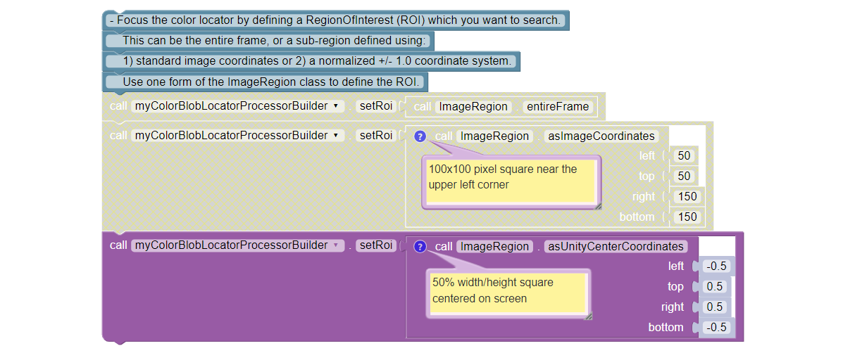
Focus the color locator by defining a RegionOfInterest (ROI) which you want to search. This can be the entire frame, or a sub-region defined using standard image coordinates or a normalized +/- 1.0 coordinate system. Use one form of the ImageRegion class to define the ROI.
Caution: changing the ROI size and/or changing the camera resolution may require an adjustment to filtering by Area. Post-filtering is covered here at this tutorial’s Explore page, and pre-filtering is covered at the following Challenge page.
Select and read the Blocks or Java section below:

Setting the ROI
In the Sample OpMode, follow the instructions at about lines 77-83 to set the desired ROI at about line 112.
.setRoi(ImageRegion.entireFrame())
.
// 100x100 pixel square near the upper left corner
.setRoi(ImageRegion.asImageCoordinates(50, 50,  150, 150))
.
// 50% width/height square centered on screen
.setRoi(ImageRegion.asUnityCenterCoordinates(-0.5, 0.5, 0.5, -0.5))
Choice of Contours
The Blocks and Java Sample OpModes give this description:
Define which contours are included. You can get ALL the contours, or you can skip any contours that are completely inside another contour. note: EXTERNAL_ONLY helps to avoid bright reflection spots from breaking up areas of solid color.
Also, the display of contours (in the previews) can be turned ON or OFF:
Turning this on helps debugging but takes up valuable CPU time.
Select and read the Blocks or Java section below:

Contour Choices
In the Sample OpMode, follow the instructions at about lines 85-92 to set the desired contour mode and drawing setting at about lines 111 and 113, respectively.
// return all contours
.setContourMode(ColorBlobLocatorProcessor.ContourMode.ALL_FLATTENED_HIERARCHY)
.
// exclude contours inside other contours
.setContourMode(ColorBlobLocatorProcessor.ContourMode.EXTERNAL_ONLY)
.
// show contours in the DS and RC previews
.setDrawContours(true)
Image Pre-Processing
The default Sample OpMode purposely blurs the camera’s image. This “pre-processing” happens before OpenCV performs Blob formation, thus affecting the contours seen in DS and RC previews.
The effect is very small (default kernel size of 5x5 pixels), but can significantly improve Blob formation, giving more useful results.
Blurring is one of three available image adjustments to improve processing results. You can experiment with these advanced tools, after studying their usage. See links at the section below called More Documentation.
The Blocks and Java Sample OpModes give this description:
Include any pre-processing of the image or mask before looking for Blobs.
There is some extra processing you can include to improve the formation of blobs. Using these features requires an understanding of how they may affect the final blobs. The “pixels” argument sets the NxN kernel size.
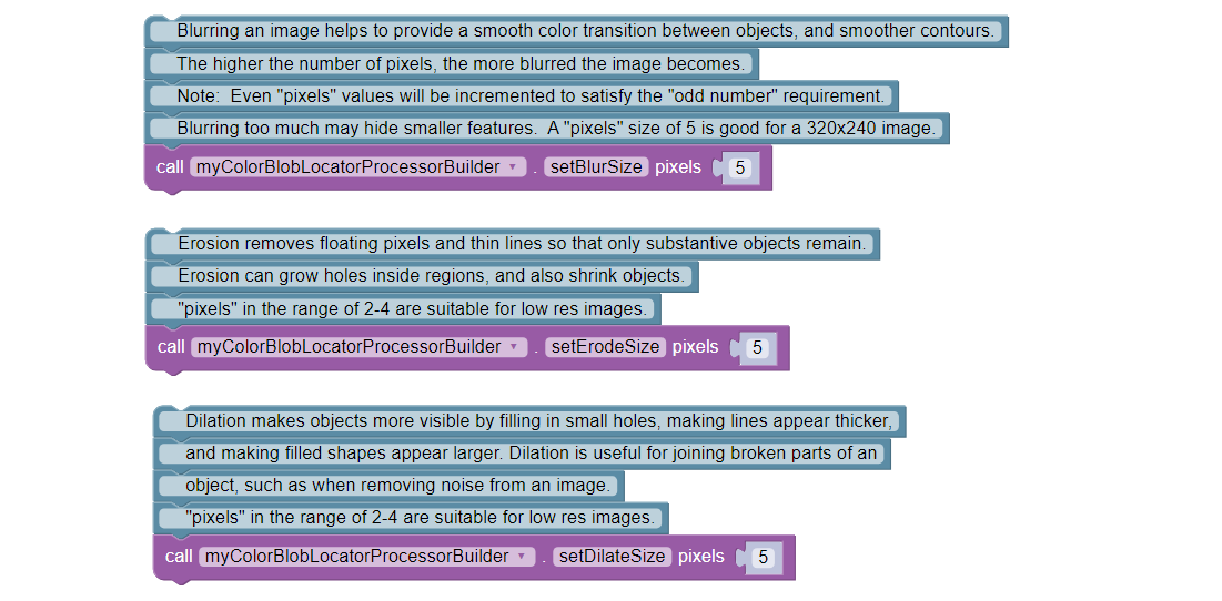
Blurring an image helps to provide a smooth color transition between objects, and smoother contours. The higher the number of pixels, the more blurred the image becomes. Note: Even “pixels” values will be incremented to satisfy the “odd number” requirement. Blurring too much may hide smaller features. A “pixels” size of 5 is good for a 320x240 image.
Erosion removes floating pixels and thin lines so that only substantive objects remain. Erosion can grow holes inside regions, and also shrink objects. A “pixels” value in the range of 2-4 is suitable for low res images.
Dilation makes objects more visible by filling in small holes, making lines appear thicker, and making filled shapes appear larger. Dilation is useful for joining broken parts of an object, such as when removing noise from an image. A “pixels” value in the range of 2-4 is suitable for low res images.
Select and read the Blocks or Java section below:

Pre-processor Options
In the Sample OpMode, follow the instructions at about lines 94-107 to set the desired pre-processing at about line 114.
.setBlurSize(int pixels)
.setErodeSize(int pixels)
.setDilateSize(int pixels)
Any of these pre-processing settings can be disabled by setting their pixel value to zero, or by removing the command.
In the FTC processor, any specified erosion is performed before dilation. This removes specular noise, then returns the remaining blobs to a size similar to their original size. (This also will not be on the final.)
Camera Resolution
The Sample OpMode uses a default camera resolution of 320 x 240 pixels, supported by most webcams and Android phone cameras. You may edit this resolution, subject to a trade-off between:
computing performance, and
image detail, possibly needed beyond ColorLocator.
Caution: changing the camera resolution and/or changing the ROI size may require an adjustment to filtering by Area. Post-filtering is covered here at this tutorial’s Explore page, and pre-filtering is covered at the following Challenge page.
The Blocks and Java Sample OpModes give this description:
Set the desired video resolution. Since a high resolution will not improve this process, choose a lower resolution that is supported by your camera. This will improve overall performance and reduce latency.
Select and read the Blocks or Java section below:

Camera Resolution
In the Sample OpMode, follow the instructions at about lines 121-123 to set the desired camera resolution at about line 131. This setting is made in the VisionPortal Builder, not the Processor Builder.
.setCameraResolution(new Size(320, 240))
Post-filter the Blob Results
After OpenCV has formed Blobs and provided results with the getBlobs()
command (in Blocks and Java), your OpMode can post-filter or reduce the
list.
Here the term “post-” means after Blob formation and after the DS and RC previews. So, you will still see contours and boxFits for all Blobs.
By default, the Sample OpMode uses a Contour Area filter of 50 pixels (minimum) to 20,000 pixels (maximum). The lower limit eliminates very small Blobs, while the upper limit is approximately the size of the default Region of Interest (ROI).
Caution: changing the ROI size and/or changing the camera resolution may require an adjustment to filtering by Area.
Tip
Remember that a Blob contour never extends beyond the ROI, although a boxFit may do so.
Why filter? A smaller list means faster processing, with fewer boxFits for your OpMode to evaluate.
You can experiment with increasing the lower limit, and observing the effect on Telemetry. Also experiment with the other filters for Density and Aspect Ratio.
The Blocks and Java Sample OpModes give this description:
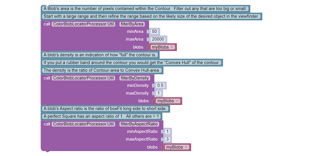
The list of Blobs can be filtered to remove unwanted Blobs. Note: All contours will be still displayed on the Stream Preview, but only those that satisfy the filter conditions will remain in the current list of “blobs”. Multiple filters may be used. Use any of the following filters.
Util.filterByArea() A Blob’s area is the number of pixels contained within the contour. Filter out any that are too big or small. Start with a large range and then refine the range based on the likely size of the desired object in the viewfinder.
Util.filterByDensity() A blob’s density is an indication of how “full” the contour is. If you put a rubber band around the contour you would get the “Convex Hull” of the contour. The density is the ratio of Contour-area to Convex Hull-area.
Util.filterByAspectRatio() A blob’s aspect ratio is the ratio of boxFit long side to short side. A perfect square has an aspect ratio of 1. All others are > 1
Select and read the Blocks or Java section below:

Post Filter
In the Sample OpMode, follow the instructions at about lines 147-164 to set the desired post-filtering at about line 166.
ColorBlobLocatorProcessor.Util.filterByArea(minArea, maxArea, blobs);
ColorBlobLocatorProcessor.Util.filterByDensity(minDensity, maxDensity, blobs);
ColorBlobLocatorProcessor.Util.filterByAspectRatio(minAspect, maxAspect, blobs);
Post-filtering commands should be placed after calling getBlobs() and
before your OpMode’s handling (or Telemetry) of the getBlobs() results.
Remember this as you incorporate these tools into your team’s larger OpModes.
Post-sort the Blob Results
After OpenCV has formed Blobs and provided results with the getBlobs()
command (in Blocks and Java), your OpMode can post-sort the list.
By default, the Sample OpMode sorts by Contour Area in descending order (largest is first). This is an internally programmed sort, not appearing in the Sample OpMode. This default is overridden or replaced by any sort specified in the OpMode.
Why sort? A sorted list means your OpMode can process Blobs in a known order, perhaps allowing your code to quickly reach a “conclusion”. Namely some logic condition (probably about boxFits) could be satisfied sooner, to exit the vision processing loop and move on to robot action.
The Blocks and Java Sample OpModes give this description:
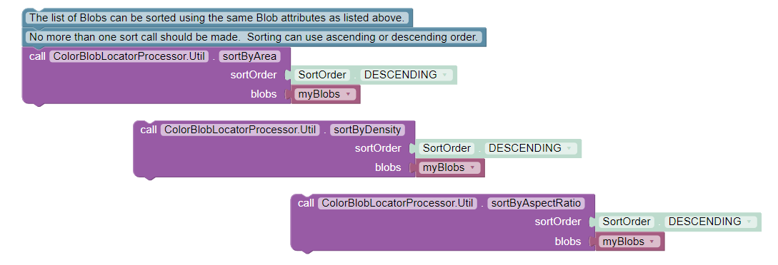
The list of Blobs can be sorted using the same Blob attributes as listed above. No more than one sort call should be made. Sorting can use ascending or descending order.
Select and read the Blocks or Java section below:

Post Sort
In the Sample OpMode, follow the instructions at about lines 169-173 to set the desired post-sorting immediately after those instructions.
ColorBlobLocatorProcessor.Util.sortByArea(SortOrder.DESCENDING, blobs);  // Default
ColorBlobLocatorProcessor.Util.sortByDensity(SortOrder.DESCENDING, blobs);
ColorBlobLocatorProcessor.Util.sortByAspectRatio(SortOrder.DESCENDING, blobs);
A post-sorting command should be placed after calling getBlobs() and
any post-filtering, and before your OpMode’s handling (or Telemetry) of the
getBlobs() results. Remember this as you incorporate these tools into your
team’s larger OpModes.
More Documentation
How does OpenCV match colors here? The upper and lower values of the target color range are used to threshold the image’s pixels and find those within the range. Technical information on thresholding is available at the OpenCV website for thresholding.
Technical information on Blur, Erosion and Dilation can be found here and at the OpenCV website for morphology.
Here’s a conceptual note from co-developer @Windwoes:
The command
getBlobs()does not initiate or perform the processing (Blob formation). The processing is happening continuously;getBlobs()just obtains a reference to the latest results.
Next, this tutorial’s Challenge page shows how to access more OpenCV features not covered in the Sample OpMode.
Then a page called Color Locator (Round Blobs) covers detection of round objects.
Questions, comments and corrections to westsiderobotics@verizon.net