Color Locator (Challenge)
Overview
This Challenge page introduces Color Locator settings that were not mentioned in the Sample OpMode. It assumes you have already followed this tutorial’s previous pages:
Discover page, to open and test the Sample OpMode
Explore page, to edit settings mentioned in the Sample OpMode
Here are the additional ColorLocator settings covered in this page:
pre-filtering, affecting Blob results and previews
pre-sorting
custom outline colors in the previews: ROI, contour, boxFit
access a boxFit’s corner points
access all vertices of a contour
access a boxFit’s size and tilt angle
create a horizonal rectangle around a tilted boxFit
access the horizontal rectangle’s size and location
Pre-Filter Intro
Here the term “pre-” means the filter criteria are implemented before the Blob formation results are passed further. Thus the DS and RC previews will not display any filtered-out contour or its boxFit. This can save CPU resources used to draw the outlines.
Likewise the resulting list of results will not include any filtered-out Blobs. A shorter list can help OpMode cycle time.
This contrasts with the post-filtering present in the Sample OpMode and discussed at this tutorial’s Explore page. Pre-filtering is a setting that persists, while post-filtering is a one-time action performed on a single set of processing results.
Teams may wish to use both. Use a pre-filter to “clean up” the preview, which can appear chaotic with potentially dozens of Blobs. Then use a post-filter to focus on the particular boxFit results of interest.
Caution: changing the ROI size and/or changing the camera resolution may require an adjustment to filtering by Area.
Pre-Filter Programming
To apply a filter setting, use two steps:
set the filter name and criteria
add that filter to the existing Processor
The “Color Blob Locator” Processor must already be created; adding a filter is not part of the Builder pattern here. A pre-filter can be added before or after the VisionPortal is built.
In general, a pre-filter setting remains in place and cannot be edited. To “change” a pre-filter, it must be removed from the Processor, then added again.
Recall from this tutorial’s Explore page, to edit settings mentioned in the Sample OpMode that filtering can be done by Contour Area, Blob Density and boxFit Aspect Ratio.
Multiple pre-filters can operate at the same time. A single common filter name could be used, if its criteria are defined, then added – then redefined, and added again, etc.
You might find it more versatile and convenient to create unique filter names, each separately managed (i.e. set criteria, add, remove, add again).
Select and read the Blocks or Java section below:
These pre-filter Blocks are in the Vision/ColorBlobLocator/Pre-processing toolbox:
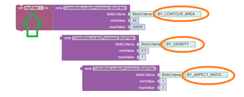
Setting a pre-filter
The Blocks in the toolbox use the same variable name myFilter (green
arrow) for the three available criteria (orange ovals). As noted above,
be careful about using a single name for different pre-filters.
For multiple pre-filters, you might prefer unique names; see the orange arrows:
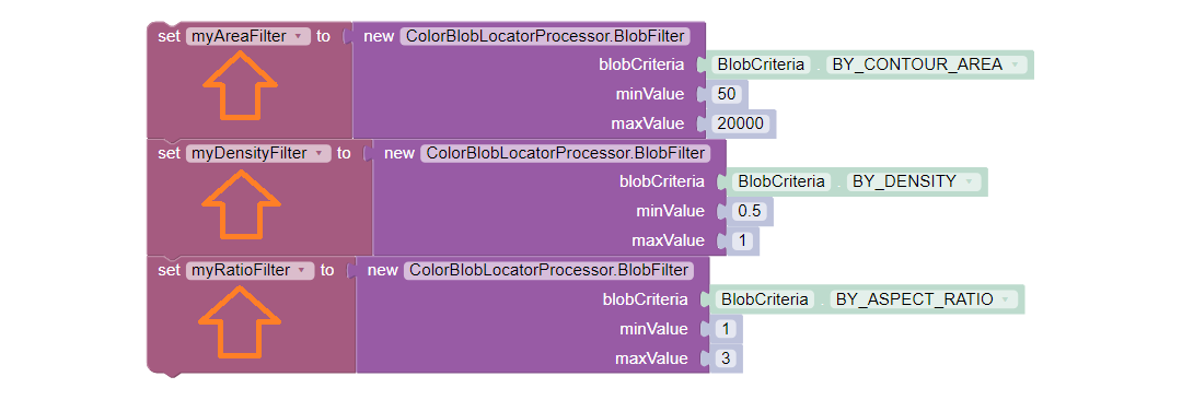
Setting 3 filters
These Blocks for adding and removing filters are in the Vision/ColorBlobLocator/Processor toolbox:

Adding and Removing a filter
Be careful to designate the correct filter to be added or removed; see the green arrows.
For multiple pre-filters, you might prefer unique names:
myAreaFilter = new BlobFilter(BlobCriteria.BY_CONTOUR_AREA, 100, 20000);
myDensityFilter = new BlobFilter(BlobCriteria.BY_DENSITY, 0.5, 1.0);
myRatioFilter = new BlobFilter(BlobCriteria.BY_ASPECT_RATIO, 1.0, 10.0);
After defining a filter’s criteria, add the filter to an already-existing Processor:
colorLocator.addFilter(myAreaFilter);
colorLocator.addFilter(myDensityFilter);
colorLocator.addFilter(myRatioFilter);
These methods can remove one or all filters from a Processor:
colorLocator.removeFilter(myAreaFilter);
colorLocator.removeFilter(myDensityFilter);
colorLocator.removeFilter(myRatioFilter);
colorLocator.removeAllFilters();
After removal, a filter can be re-added to the Processor.
Pre-sort
Here the term “pre-” also means the sort criteria are already established, and applied to the results of the Blob formation process.
This works the same as the post-sorting mentioned in the Sample OpMode and discussed at this tutorial’s Explore page. Pre-sorting is a setting that persists, while post-sorting is a one-time action performed on a single set of processing results.
Only one sort (the last one applied) affects the final list of results provided for the OpMode to evaluate. Thus there is no benefit to using both pre-sort and post-sort.
To apply a sort, use two steps:
define the sort name and criteria
apply that sort to the existing Processor
The “Color Blob Locator” Processor must already be created; adding a sort is not part of the Builder pattern here. A pre-sort can be added before or after the VisionPortal is built.
In general, a pre-sort setting remains in place and cannot be removed or
edited. To “change” a sort, simply define and apply another one, with the same
or a unique name. The later setSort() will be in effect.
Reminder from this tutorial’s Explore page: by default, the Sample OpMode sorts by Contour Area in descending order (largest is first). This is an internally programmed sort, not appearing in the Sample OpMode. This default is overridden or replaced by any pre-sort or post-sort specified in the OpMode.
Select and read the Blocks or Java section below:
These pre-sort Blocks are in the Vision/ColorBlobLocator/Pre-processing toolbox:

Selecting the Sort Criteria
This Block for applying the named pre-sort is in the Vision/ColorBlobLocator/Processor toolbox:

Setting the Sort Criteria
A generic pre-sort name works well, since only one sort can be in effect at a time:
mySort = new BlobSort(BlobCriteria.BY_CONTOUR_AREA, SortOrder.ASCENDING);
If you are experimenting with different pre-sort criteria, you might consider unique names:
myAreaSort = new BlobSort(BlobCriteria.BY_CONTOUR_AREA, SortOrder.ASCENDING);
myDensitySort = new BlobSort(BlobCriteria.BY_DENSITY, SortOrder.ASCENDING);
myRatioSort = new BlobSort(BlobCriteria.BY_ASPECT_RATIO, SortOrder.ASCENDING);
After defining a sort’s criteria, apply the pre-sort to an already-existing Processor:
colorLocator.setSort(mySort);
Preview Colors
You can specify custom colors for the preview outlines of:
Region of Interest (ROI)
Blob contour
boxFit rectangle
Select and read the Blocks or Java section below:
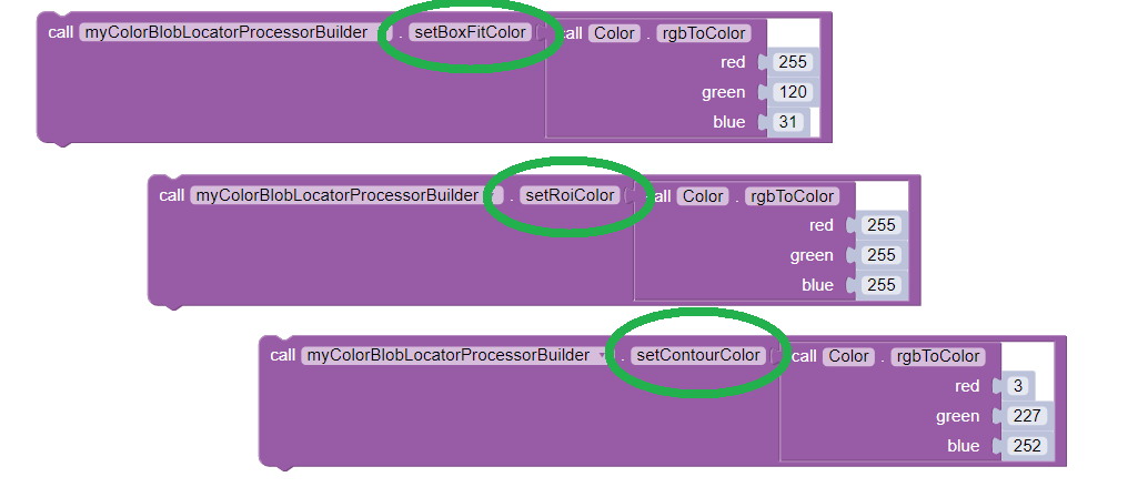
Setting custom outline colors
Import the Color class if needed, then add any of the .set...
methods to the Processor Builder pattern:
import android.graphics.Color;
.
.
.setBoxFitColor(Color.rgb(255, 120, 31))
.setRoiColor(Color.rgb(255, 255, 255))
.setContourColor(Color.rgb(3, 227, 252))
Use your own custom values, only from the RGB Color Space. See the separate tutorial page called Color Spaces.
boxFit Corners
An OpMode can access the four corner points of a boxFit rectangle.
Select and read the Blocks or Java section below:
This Blocks Function retrieves, stores and displays the 4 corner points of the instant boxFit being processed by the OpMode:
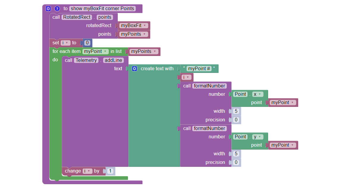
Displaying Corner Points via Telemetry
The .points and Point.x and Point.y Blocks are in the
“Vision/ColorBlobLocator/Blob data” toolbox.
The Function uses its own For Loop to cycle through the myPoints
List of 4 points, clockwise from top left corner.
This Function operates inside the Sample OpMode’s For Loop of all
Blob results. The instant myBoxFit is the one being processed,
returned from the preceding .BoxFit Block.
This Java code retrieves, stores and displays the 4 corner points of the instant boxFit being processed by the OpMode:
// Display boxFit.points(), an array of the box's four (X, Y) corner points,
// clockwise from top left corner.
Point[] myBoxCorners = new Point[4];
boxFit.points(myBoxCorners);
// this points() method does not return values, it populates the argument
for (int i = 0; i < 4; i++)
{
    telemetry.addLine(String.format("boxFit corner %d (%d,%d)",
    i, (int) myBoxCorners[i].x, (int) myBoxCorners[i].y));
}
This code operates inside the Sample OpMode’s For Loop of all Blob
results. The instant boxFit is the one being processed, returned
from the preceding getBoxFit() method.
Contour Vertices
Blob contours are irregular and hard to process in code; it’s easier to work with boxFit rectangles.
But the contour’s outer points can be accessed by an OpMode. The result is a list of (X, Y) coordinates, with origin at the top left corner of the camera’s image. X increases to the right, Y increases downward.
Select and read the Blocks or Java section below:
The following Blocks Function retrieves, stores and displays a List of all the vertex Points of the contour of the instant Blob being processed by the OpMode.
The List can be as short as 4 values, or dozens of values for jagged contours.
Note that the .points Block (used above for boxFit corners) retrieves
and stores the List within the same Block. This .ContourPoints Block
only retrieves the List, to be assigned to a separate variable Block.
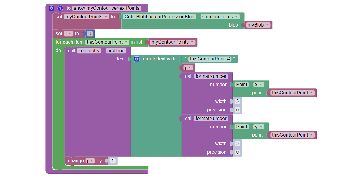
Getting the list of contour points
The .ContourPoints and Point.x and Point.y Blocks are in the
“Vision/ColorBlobLocator/Blob data” toolbox.
The Function uses its own For Loop to cycle through the
myContourPoints List, of undetermined length (could be very long).
This Function operates inside the Sample OpMode’s For Loop of all
Blob results. The instant myBlob is the one being processed by that
outer For Loop.
This Java code retrieves, stores and displays a List of all the vertex Points of the contour of the instant Blob being processed by the OpMode.
import org.opencv.core.Point;
.
.
// Display getContourPoints(), an array of the contour's many (X, Y) vertices
Point[] myContourPoints;
myContourPoints = b.getContourPoints();
int j = 0;
for(Point thisContourPoint : myContourPoints)
{
    telemetry.addLine(String.format("contour vertex %d (%d,%d)",
          j, (int) thisContourPoint.x, (int) thisContourPoint.y));
          j += 1;
}
This Function operates inside the Sample OpMode’s For Loop of all
Blob results. The instant Blob b is the one being processed by that
outer For Loop.
Not covered here is one feature available in Java only:
MatOfPoint myContour = getContour()
This method returns a matrix unique to the OpenCV library. The matrix object can convert itself to an array, as follows:
MatOfPoint myContour;
Point[] myContourPoints;
myContour = b.getContour();
myContourPoints = myContour.toArray();
This code seems to give the same set of points as getContourPoints()
shown above.
boxFit Size and Angle
These simple fields were not demonstrated in the Sample OpMode.
The boxFit size variable contains two fields which must be accessed individually, as shown below.
If the boxFit is horizontal (parallel to the ROI), its angle might be 0 or 90 degrees, often jumping between the two values. At 90 degrees, height and width become switched. Your OpMode code needs to account for this scenario.
Likewise, the boxFit angle is sometimes reported as clockwise from vertical, rather than counterclockwise from horizontal. More discussion is here.
Select and read the Blocks or Java section below:
These Blocks are in the “Vision/ColorBlobLocator/Blob data” toolbox.
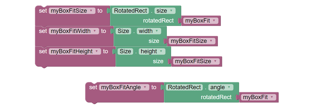
boxFit properties
Here’s a modified version of the Sample OpMode’s telemetry code, to display only the size and angle of the instant boxFit being processed.
org.opencv.core.Size myBoxFitSize;
for(ColorBlobLocatorProcessor.Blob b : blobs)
{
             RotatedRect boxFit = b.getBoxFit();
             myBoxFitSize = boxFit.size;
             telemetry.addData("width", myBoxFitSize.width);
             telemetry.addData("height", myBoxFitSize.height);
             telemetry.addData("angle", boxfit.angle);
}
The Java class Size here is different than another class of the same
simple name. OnBot Java and Android Studio do not allow imports of
identical simple classnames.
In fact OnBot Java will not allow the import of this version, even if the other version (android.util.Size) is not used in the OpMode. Instead, declare the variable with the full classname, as shown in the first line above.
Horizontal Rectangle
You might prefer to process only horizontal best-fit rectangles, parallel to the ROI, not tilted.
OpenCV can generate a best-fit rectangle for a boxFit, whether tilted or not. This is not a “forced horizonal” boxFit, rotated in place. The new horizontal rectangle simply touches and encloses the outer corners of the boxFit.
If the boxFit is tilted, the new horizontal rectangle will be larger. If the boxFit already had an angle of 0 (or 90) degrees, the new rectangle will be identical.
In Blocks and Java, the command boundingRect() accepts a boxFit of type
RotatedRect and returns a horizontal rectangle of type Rect. The new
rectangle is not drawn or depicted in the preview.
Select and read the Blocks or Java section below:
These Blocks are in the “Vision/ColorBlobLocator/Blob data” toolbox.
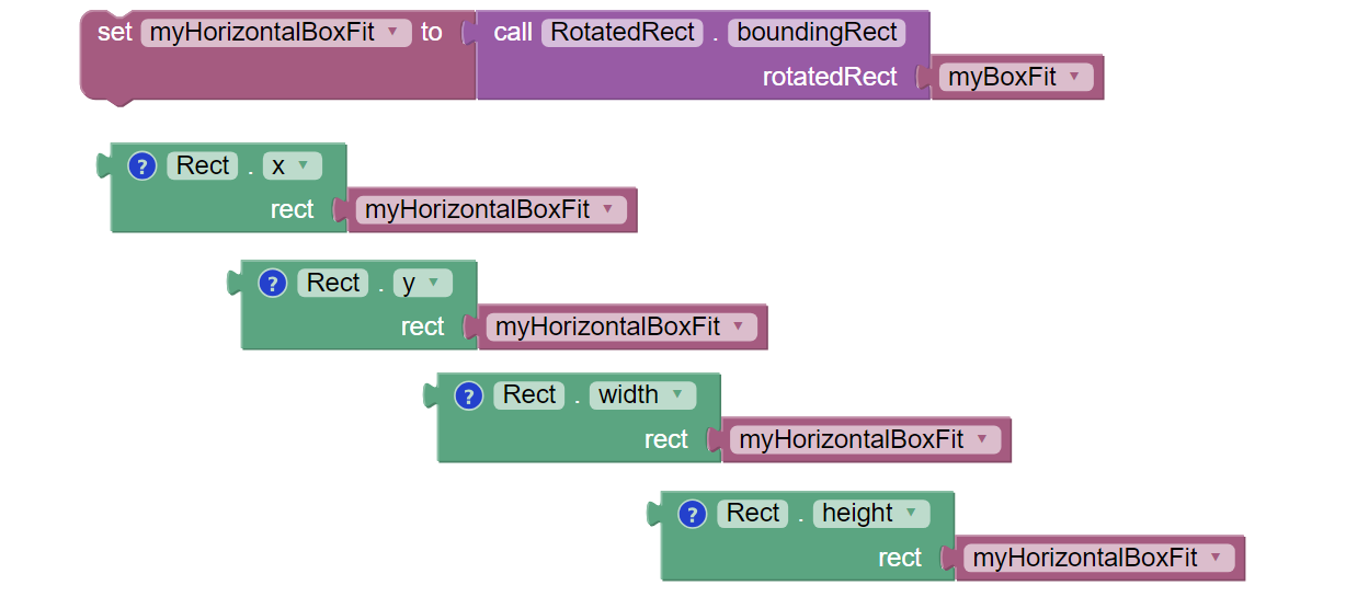
Defining the horizontal box
The (X, Y) values are the top left corner of the new horizontal rectangle, in the full image reference frame.
Here’s a modified version of the Sample OpMode’s telemetry code, to display only the top left corner and size of the horizontal rectangle around the boxFit being processed.
import org.opencv.core.Rect;
.
.
for(ColorBlobLocatorProcessor.Blob b : blobs)
{
                RotatedRect boxFit = b.getBoxFit();
                Rect myHorizontalBoxFit = boxFit.boundingRect();
                telemetry.addData("top left X", myHorizontalBoxFit.x);
                telemetry.addData("top left Y", myHorizontalBoxFit.y);
                telemetry.addData("width", myHorizontalBoxFit.width);
                telemetry.addData("height", myHorizontalBoxFit.height);
}
In this case, OnBot Java and Android Studio found no conflicts with the
import of class Rect.
Pay attention to classes and fields:
boxFit is of Java type
RotatedRect, even though it’s not usually rotatedthe new method
boundingRect()returns an object of typeRectthe
SizeandRectclasses both have fields namedheightandwidth
Advanced Development
Searching for multiple colors is possible by building multiple processors and adding them to the same VisionPortal. This allows different ROIs, for example, that can overlap if desired.
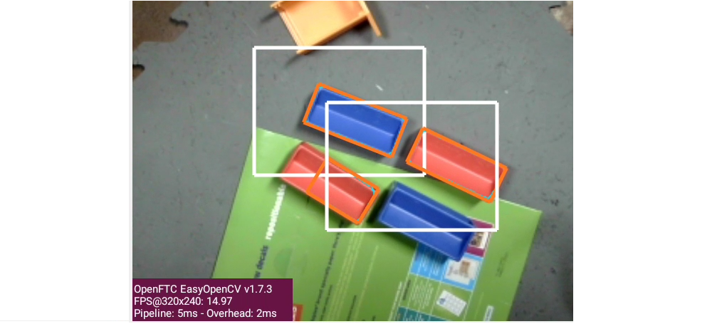
Using two processors
This ends the tutorial’s 3 pages on ColorLocator:
The final page of this tutorial provides optional info on Color Spaces.
Best of luck as you apply these tools to your Autonomous and TeleOp OpModes!
Questions, comments and corrections to westsiderobotics@verizon.net