Color Locator (Round Blobs)
Overview
FTC’s “Color Locator” now offers a best-fit circle called circleFit, an alternate to the best-fit rectangle (“boxFit”) described in previous sections of this tutorial.
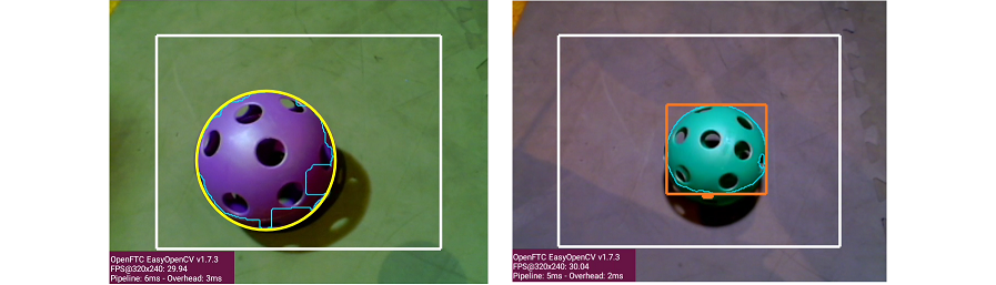
circleFit versus boxFit detection
This page describes the new Sample OpMode called ConceptVisionColorLocator_Circle, in FTC Blocks and Java. These notes assume familiarity with the original Sample OpMode, now called ConceptVisionColorLocator_Rectangle.
The new _Circle Sample uses these settings for convenient processing of DECODE Artifacts:
increase Erode and Dilate areas from 5 to 15 pixels
change order of Erode and Dilate
draw
circleFitpreviewTelemetry shows only Circularity, Radius and Center
As an alternate, the _Rectangle Sample OpMode can still be used and modified to process objects of any shape, including round balls, with access to the same attributes.
Quick Start
Note
This and other steps here were previously described in detail, starting with the page called Color Locator - Discover.
In FTC Blocks or Java, create a new Autonomous OpMode from the Sample
ConceptVisionColorLocator_Circle.On the Driver Station, select the OpMode that you just saved or built.
Turn off the automatic 30-second match timer (green slider). Aim the camera at a DECODE Purple Artifact, or a picture of one.
Touch INIT only. The OpMode should give Telemetry showing the results of one or more Blobs:
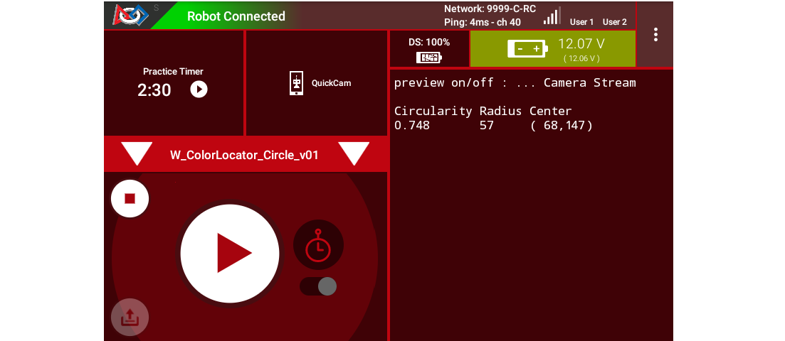
Circle Fit Telemetry from ConceptVisionColorLocator_Circle sample
In this example, Telemetry reports only one Blob in the Region of Interest (ROI), of the default target color ARTIFACT_PURPLE.
Note
The Sample OpModes _Circle and _Rectangle also offer the custom color ARTIFACT_GREEN.
Move the camera around, and watch the Telemetry area on the Driver Station screen. It may sometimes show more lines of Blob data, and sometimes show no Blob data at all.
It’s working! Your camera is working as a color locator. Think about how to use this in the DECODE game.
DS and RC Previews
Before studying the telemetry data more closely (below), make sure you can see the previews of the OpenCV results. Previewing is essential for working with vision code.
The Driver Station (DS) “snapshot” preview is available at the Camera Stream menu choice, with the OpMode in INIT.
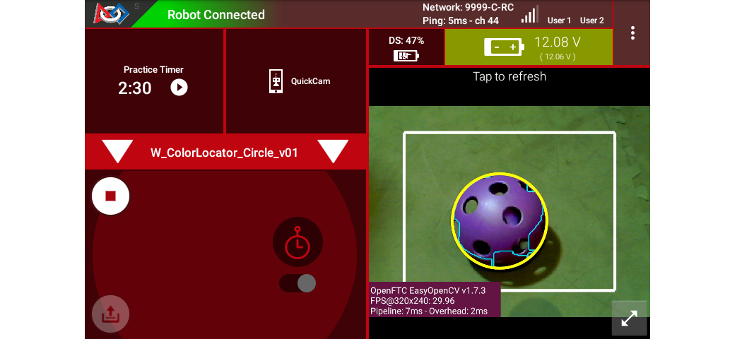
Driver Station Camera Stream Image showing a successful Circle Fit
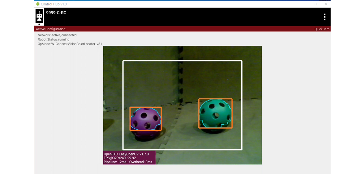
The Robot Controller (RC) device makes a video preview called LiveView. For a REV Control Hub, this video can be seen on an HDMI monitor or with open-source scrcpy (called “screen copy”):
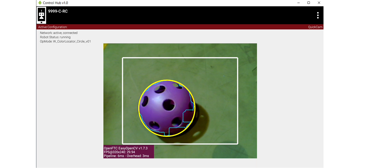
Robot Controller LiveView showing a successful Circle Fit
For both previews, the white rectangle is the Region of Interest (ROI), and the thin green jagged line is the Blob’s contour (fully inside the ROI).
The yellow circle is the new circleFit : the smallest circle that encloses the contour. The circleFit is not required to stay inside the ROI.
Basic Telemetry Data
Here again is some DS telemetry from the new _Circle Sample:
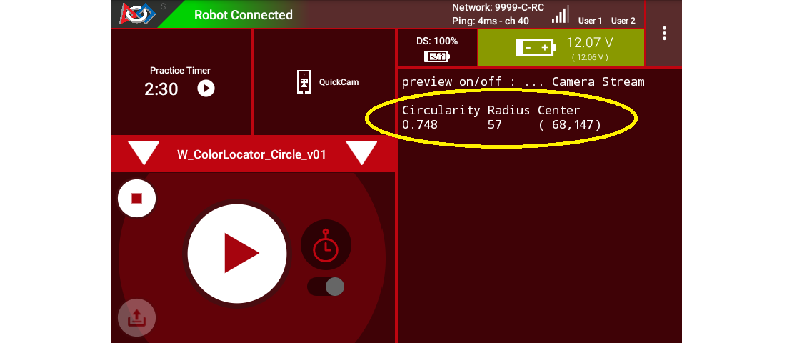
Driver Station Telemetry Data from _Circle sample
The first column shows the Circularity of the Blob contour (not its circleFit). This is calculated from the Blob’s area and perimeter. A higher value, closer to 1, indicates a more circular contour.
The second column shows the circleFit’s Radius , an indicator of size. Again, the circleFit is not required to stay inside the ROI.
The third column shows the (X, Y) position of the circleFit’s Center. With the origin at the full image’s top left corner, X increases to the right and Y increases downward.
The Blob’s Area is available but not displayed here. The Sample OpMode uses a filter to show Blobs with area between 50 and 20,000 pixels. Another filter shows Blobs with circularity greater than 0.6. Filters can be customized, as described in the Sample’s comments.
For multiple Blobs, the Sample lists Telemetry using only the built-in default sort by area (largest is first). Other sorting choices are available, described in the Sample’s comments.
The Blob’s Density is also available but not displayed here. From the Sample’s comments:
Tip
A blob’s density is an indication of how “full” the contour is. If you put a rubber band around the contour you would get the “Convex Hull” of the contour. The density is the ratio of Contour-area to Convex Hull-area.
Using CircleFit Data
A team’s Autonomous code can evaluate circleFit data to navigate or guide the robot on the field.
The circleFit Radius (indicating size) can help estimate the distance from the camera lens to the Artifact. Calibrate this at your home field, based on the known physical size of an Artifact.
Tip
Fortunately, a round ball gives no complications of perspective, like the tapered image of a rectangular object. An unobstructed, well-lit Artifact can reliably appear as a circle.
The circleFit Center (X, Y) can help estimate the Artifact’s position relative to the camera on the robot. Calibrate this at your home field, based on known test locations and distances.
With these estimates of distance and position, the robot can be programmed to approach and collect the Artifact, or perhaps navigate elsewhere on the field.
Manage the Previews
The FTC SDK handles the two preview shapes differently:
boxFitis enabled by defaultcircleFitis disabled by default
The _Circle sample turns off the boxFit with this Builder command:
.setBoxFitColor(0) // Disable the drawing of rectangles
The “zero” is not a color, but an indicator to disable a preview drawing.
Conversely, the _Circle sample turns on the circleFit with this Builder command:
.setCircleFitColor(Color.rgb(255, 255, 0)) // Enable the drawing of a circle around blobs
This default color is yellow, but any color space and values may be specified.
Both previews can be disabled or enabled at the same time. The default boxFit color can be modified from its default shade of red: Color.rgb(255, 120, 31).
Manage Erode and Dilate
Erosion and Dilation are morphological operations: pre-processing steps to improve vision recognition.
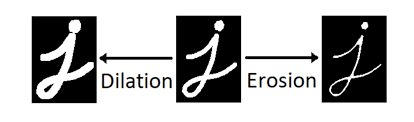
Dilation and Erosion morphological operations
The Sample’s comments describe this Builder command:
.setMorphOperationType(MorphOperationType morphOperationType)This defines the order in which the Erode/Dilate actions are performed.
OPENING: Will Erode and then Dilate which will make small noise blobs go away
CLOSING: Will Dilate and then Erode which will tend to fill in any small holes in blob edges.
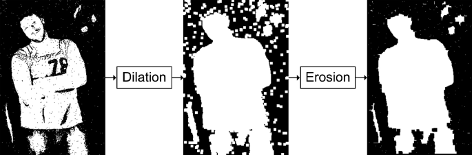
Dilation and Erosion examples using an image
The original _Rectangle Sample used “Erode then Dilate”, effective for most applications. This new _Circle Sample uses “Dilate then Erode”, which improves detection of a DECODE Artifact (smoothes edges of its large holes). It also uses Erode and Dilate sizes of 15 pixels, larger than typical 5 pixels.
Improving Results
FTC teams can adjust settings to improve results based on:
webcam model
webcam position on robot (lookdown angle)
Artifact clustering or blocked views
planned method of approach and collection
game strategy (which Artifacts, from which positions)
possible presence of other robots
static vs. moving targets
venue lighting and potential shadowing
OpMode loop rate
In the case of adjacent or overlapping Artifacts, boxFit might offer more useful data than circleFit.
The new _Circle Sample offers all of the settings from the _Rectangle Sample. These can be adjusted for different results:
camera resolution, default 320x240
Region of Interest, default central 3/4
target color range, predefined or custom
type of contour, default External Only
preview drawings, including circleFit and/or boxFit
Blur size, default 5 pixels
Erode size, default 15 pixels
Dilate size, default 15 pixels
order of operation, default Dilate then Erode
Results can be filtered in multiple ways:
Contour Area
Density
Aspect Ratio (for boxFit)
Arc Length
Circularity
Telemetry Results can be sorted by any of the above attributes. See the Sample’s comments for guidance.
Lighting Challenges
Robotics vision is highly sensitive to field lighting. The FTC VisionPortal offers software tools called Camera Controls to help address varying or “difficult” lighting conditions.
If needed, see the separate tutorial called FTC VisionPortal Camera Controls.
More detail on these controls is provided in an older tutorial - ftc-docs Webcam Controls; disregard the TensorFlow references.
These tools can help with Color Processing and AprilTag Detection.
Lastly, some webcams perform automatic color correction, under changing lighting conditions. If you observe this in Previews, make adjustments as needed.
OpMode Development
You should eventually use or adapt program elements from the Color Locator _Circle or _Rectangle Sample, to become part of your team’s Autonomous (or TeleOp) OpMode.
An early choice is: how long should the processing (looping) continue, before using the extracted data for robot action? What should be the criteria to exit a loop, and which data should be used for subsequent calculations and movement?
You may find it useful to learn about Datalogging. Output this OpMode’s Color Processor data to a file, then perhaps to a spreadsheet. Careful review may reveal which data are useful, rather than trying to observe the “jumpy” preview and Telemetry results.
Also, you may want to track multiple colors, like this:
Tracking multiple colors within a single ROI
This is quite possible, by setting up multiple processors, all incorporated into the Vision Portal. You may find it helpful to first organize the Sample OpMode into methods (or Functions for FTC Blocks): one for the processor and one for Telemetry. Then it should be straightforward to create parallel methods or Functions.
Summary
FTC’s “Color Locator” now offers a best-fit circle called circleFit, an alternate to the best-fit rectangle (“boxFit”) described in previous sections of this tutorial.
This new feature is shown in the Sample OpMode called ConceptVisionColorLocator_Circle, in FTC Blocks and Java. This sample exists alongside the existing _Rectangle Sample OpMode.
The new _Circle Sample uses certain settings for convenient processing of DECODE Artifacts, as a starting point for teams. Many choices are provided to optimize results for a team’s robot and strategy.
This ends the tutorial’s 4 pages on ColorLocator:
The final page of this tutorial provides optional info on Color Spaces.
Best of luck as you apply these tools to your Autonomous and TeleOp OpModes!
Questions, comments and corrections to westsiderobotics@verizon.net