Adding an Expansion Hub
Introduction
A single REV Robotics Control or Expansion Hub has a limited amount of input/output (I/O) ports available. In some instances, you might want to use more devices than there are ports available. For these instances you might need to connect an Expansion Hub to your first Hub to add more I/O ports.
This document describes how to connect and configure an additional Expansion Hub for use in the FIRST Tech Challenge. Note that the FIRST Tech Challenge Competition Manual limits the maximum number of Control or Expansion Hubs on a single robot to two.
Equipment Needed
To follow along with the instructional steps in this document, you will need the following items:
Required Item(s) |
Image |
|---|---|
REV Robotics Driver Hub (REV-31-1596) |
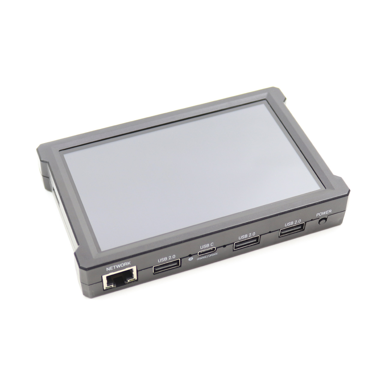
|
REV Robotics Switch, Cable, & Bracket (REV-31-1387). |
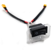
|
REV Robotics Tamiya to XT30 Adapter Cable (REV-31-1382). |
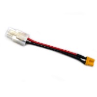
|
FIRST-approved 12V Battery (such as Tetrix W39057). For a list of FIRST-approved 12V batteries, refer to the current Competition Manual. |
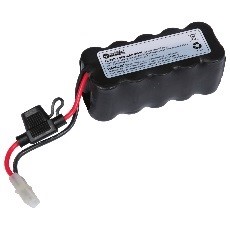
|
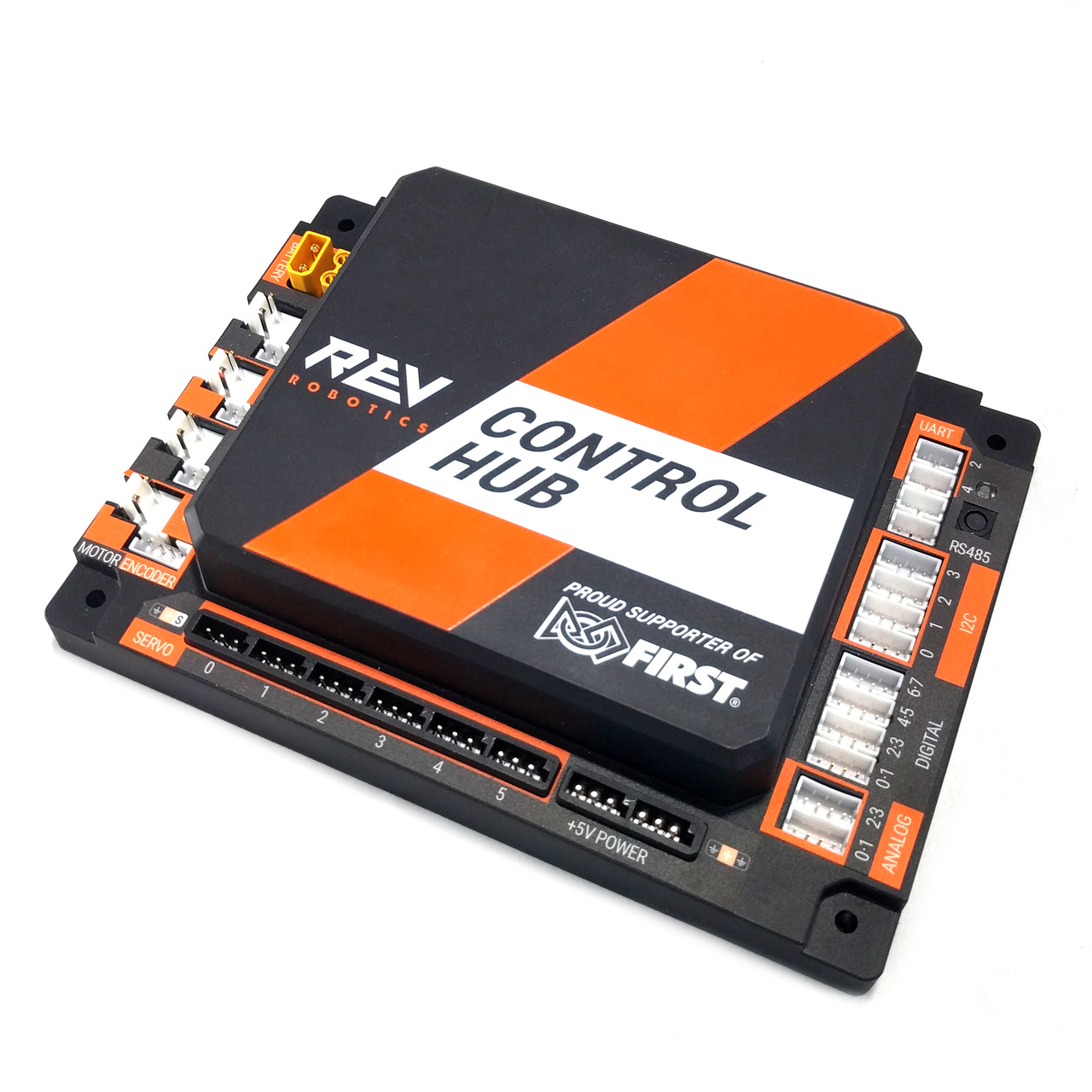
REV Robotics Control Hub (REV-31-1595). |
|
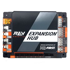
REV Robotics Expansion Hub (REV-31-1153). |
|
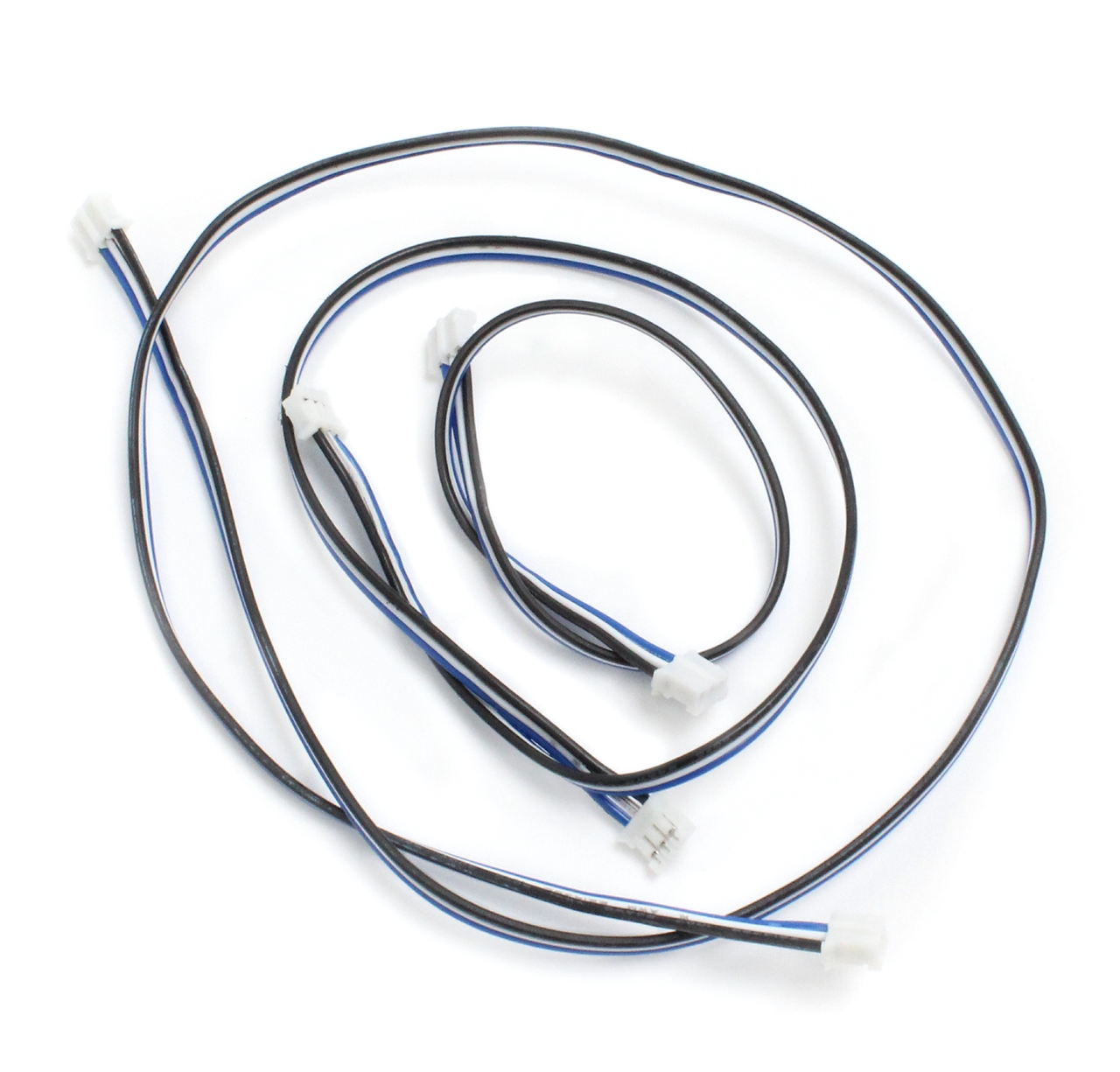
REV Robotics (or equivalent) 3-Pin JST PH Cable (REV-35-1414, 3 pack shown but only one needed). |
|
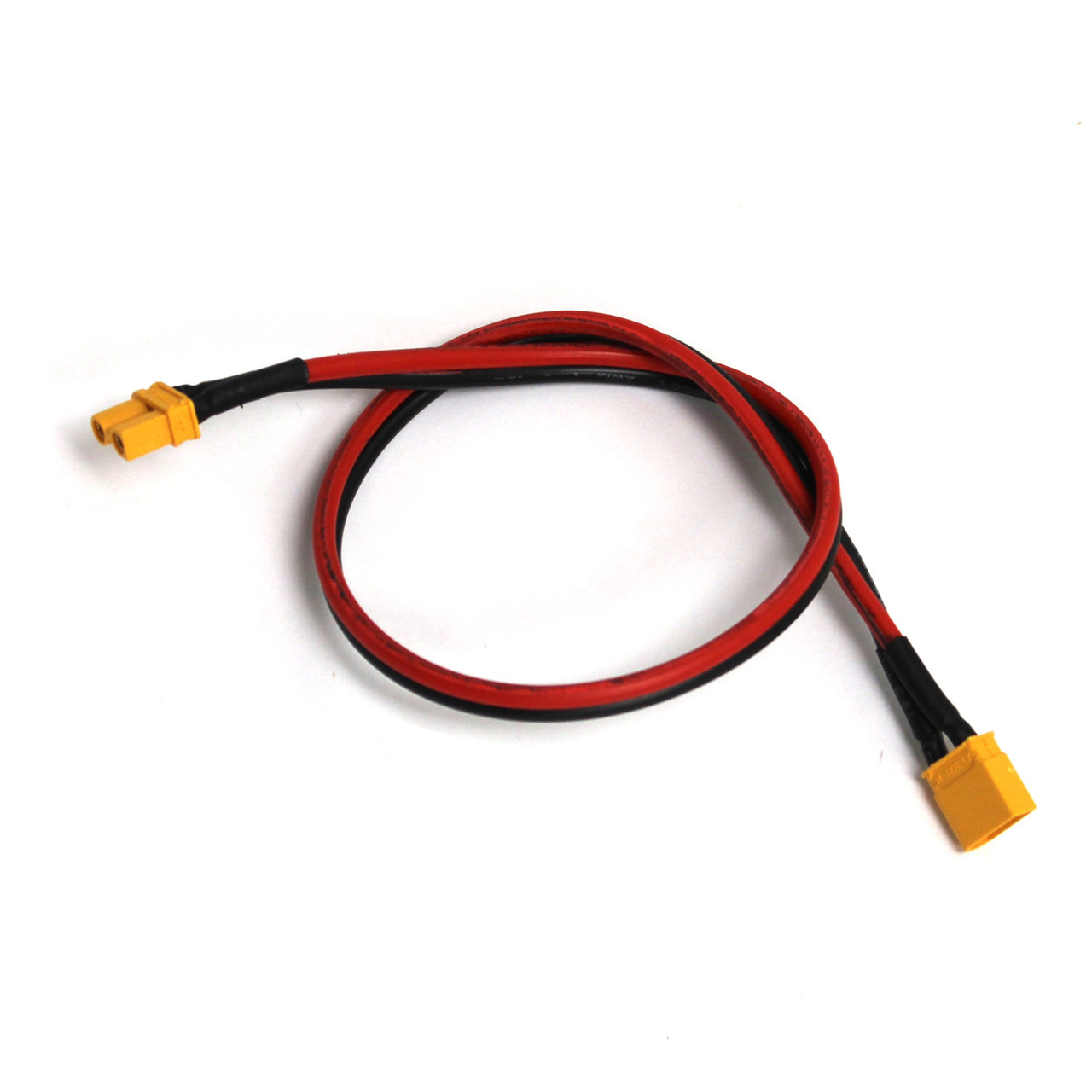
REV Robotics XT30 Extension Cable (REV-31-1394). |
|
Connecting the Expansion Hub
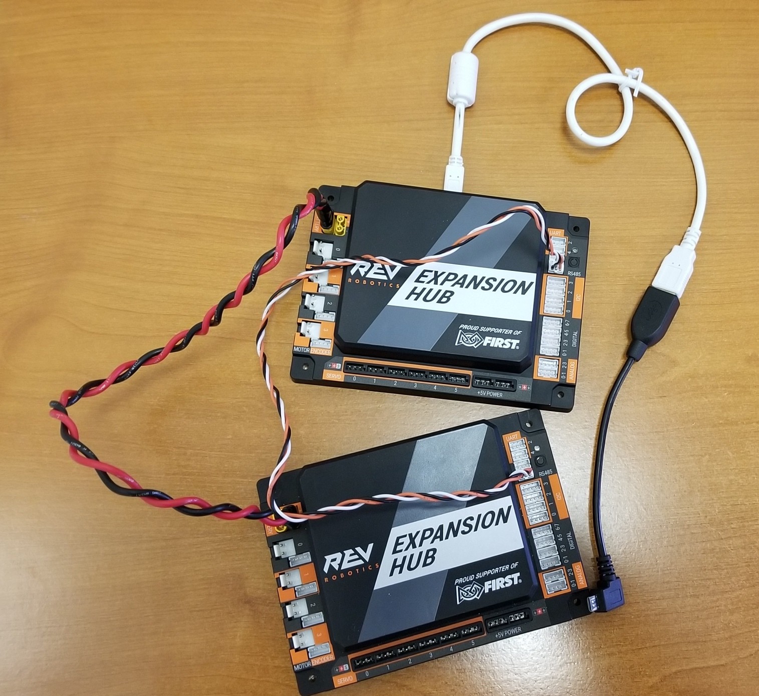
1. The first step is to use the 3-pin JST PH cable and the XT30 cable to daisy chain the two Hubs together. Before you do this, ensure that neither Hub is powered on.
Use the XT30 extension cable to connect an XT30 power port on the Control Hubs to an XT30 power port on the other Expansion Hub.
<INSET IMAGE>
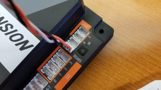
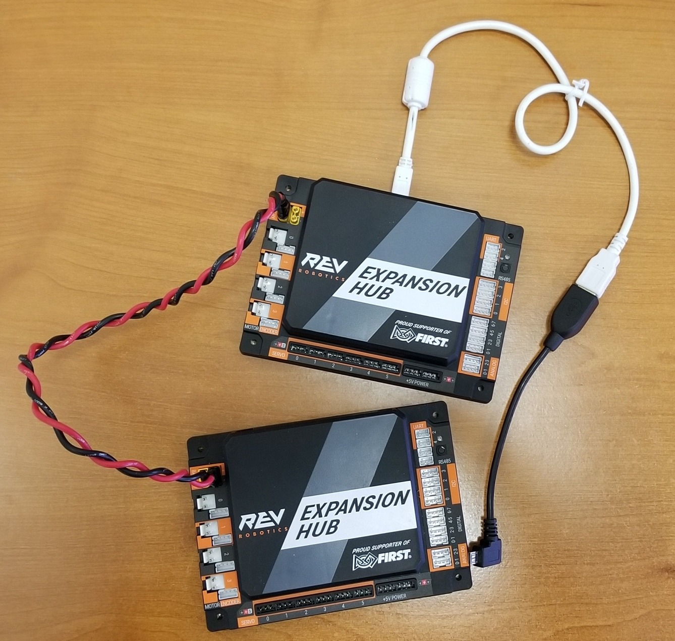
2. The Control Hub and Expansion Hub use the RS-485 serial bus standard to communicate between devices. You can use the 3-pin JST PH cable to connect one of the ports labeled “RS485” on the Control Hub to one of the ports labeled “RS485” on the Expansion Hub.
<INSERT IMAGE>
Note that it is not important which “RS485” port that you select on the Expansion Hub or Control Hub. Either port should work.
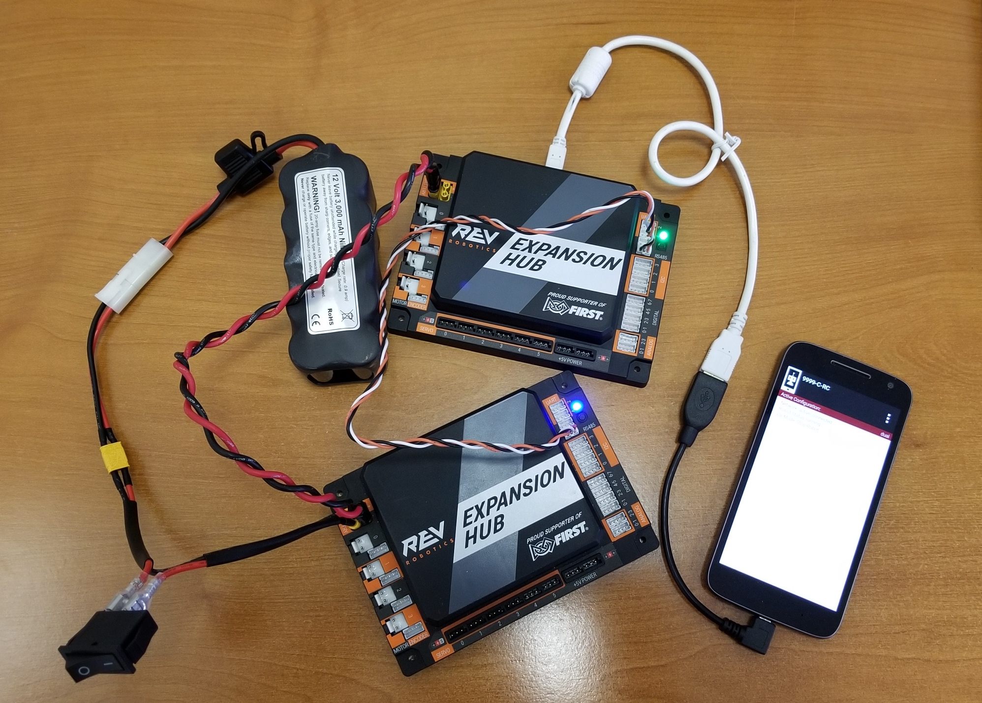
3. Once you have the two devices daisy chained together (12V power and RS-485 signal) you can connect the battery and power switch, and power on the devices.
<INSERT IMAGE>
Configuring Both devices
If you successfully daisy chained your Expansion Hub and Control Hub, then you should be able to create a new configuration file that includes both devices.
Note: If you already have a configuration that contains just the Control Hub, you can add the Expansion Hub by editing the configuration and pressing the “Scan” button.
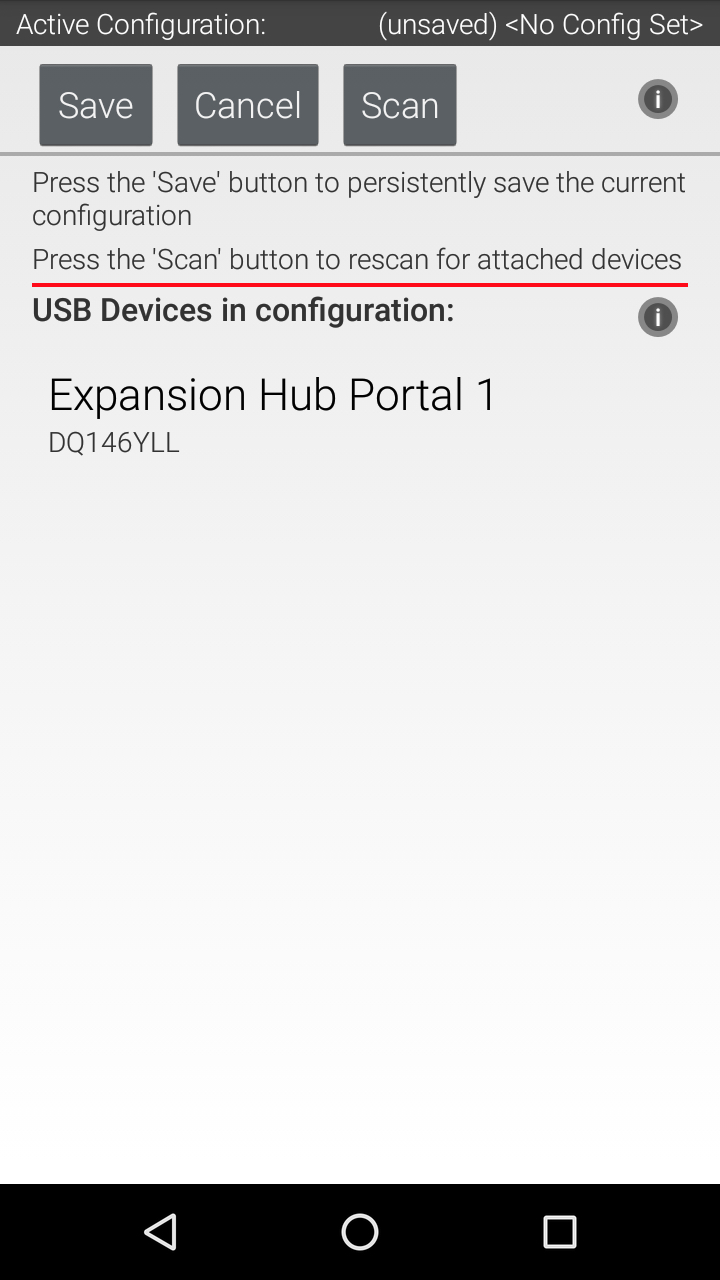
Connect your Driver Hub to the Control Hub’s WiFi network and select the Configure Robot option from the Driver Station app. Press the New button to create a new configuration file. When you first scan for hardware, your Robot Controller should detect the embedded Control Hub. The Robot Controller will automatically label this device as an Control Hub “Portal”. The Robot Controller will communicate through this portal to the individual Hubs.
<INSERT IMAGE>
If you click on the Portal item in the configuration screen, you should see both the Control Hub and the Expansion Hub listed.
<INSERT IMAGE>
You can save this configuration file and return to the main screen of the Driver Station. After the robot has been restarted, both Hubs should have a solid green LED. On the Expansion Hub, the LED should blink blue every ~5 seconds.
Congratulations, you are now ready to use your combination of Control and Expansion Hubs! You can configure and operate these Hubs as you would an individual Hub.
Using Two Expansion Hubs
Teams without access to a Control Hub may use two Expansion Hubs on their robot.
Additional Equipment Needed
There is some additional equipment required for teams who aren’t using a Control Hub on their robot.
Required Item(s) |
Image |
|---|---|
A FIRST-approved Android smartphone with the FTC Robot Controller app installed. For a list of FIRST-approved Android smartphones, refer to the current Competition Manual. |

|
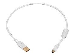
USB Type A male to type mini-B male cable. |
|
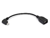
Micro USB OTG adapter. |
|
An additional REV Robotics Expansion Hub (REV-31-1153). |
|
Changing the Address of an Expansion Hub
You can use the Advanced Settings menu of the Robot Controller App to change the address of any connected Expansion Hubs.
Important Note: If both of your Expansion Hubs have the same address or were just removed from the box (by default, the address is set to 2), you need to change the address of one of them _before_ connecting them together. This guide assumes that you will be setting the address of the first Expansion Hub before connecting the second Expansion Hub.
With your first Expansion Hub connected to the 12V battery and to the Robot Controller, launch the Settings menu from the Robot Controller app (note you can also do this from the Driver Station app, if the DRIVER STATION is paired to the Robot Controller).
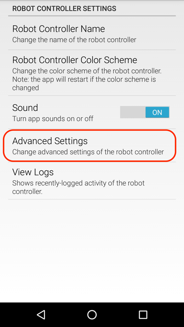
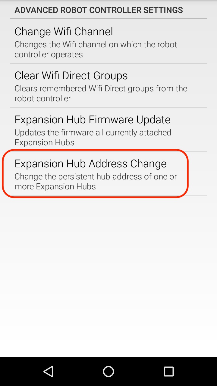
Select the Advanced Settings item to display the Advanced Settings menu.
2. Then select the Expansion Hub Address Change item to display the Expansion Hub address screen.
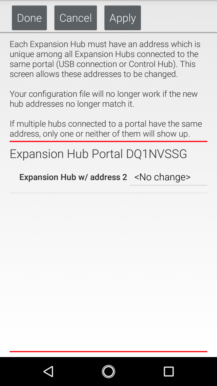
3. The USB serial number of the Expansion Hub and its currently-assigned address should be displayed.
Important Note: If any Expansion Hubs that are physically connected and powered are not displayed, there may be an address conflict. If this happens, disconnect all Expansion Hubs except the one whose address you want to change.
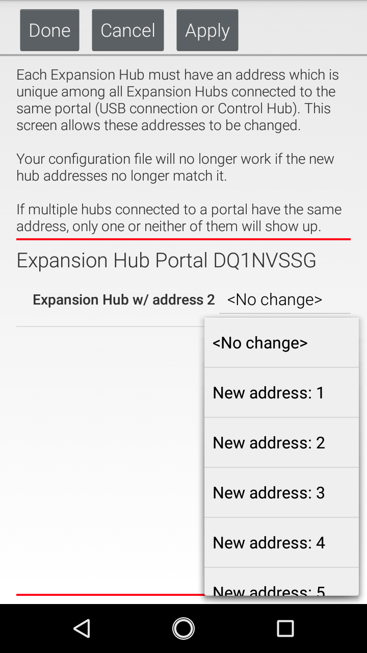
4. Use the dropdown list control on the right hand side to change an Expansion Hub’s address. Addresses that conflict with other currently-connected Expansion Hubs won’t be available.
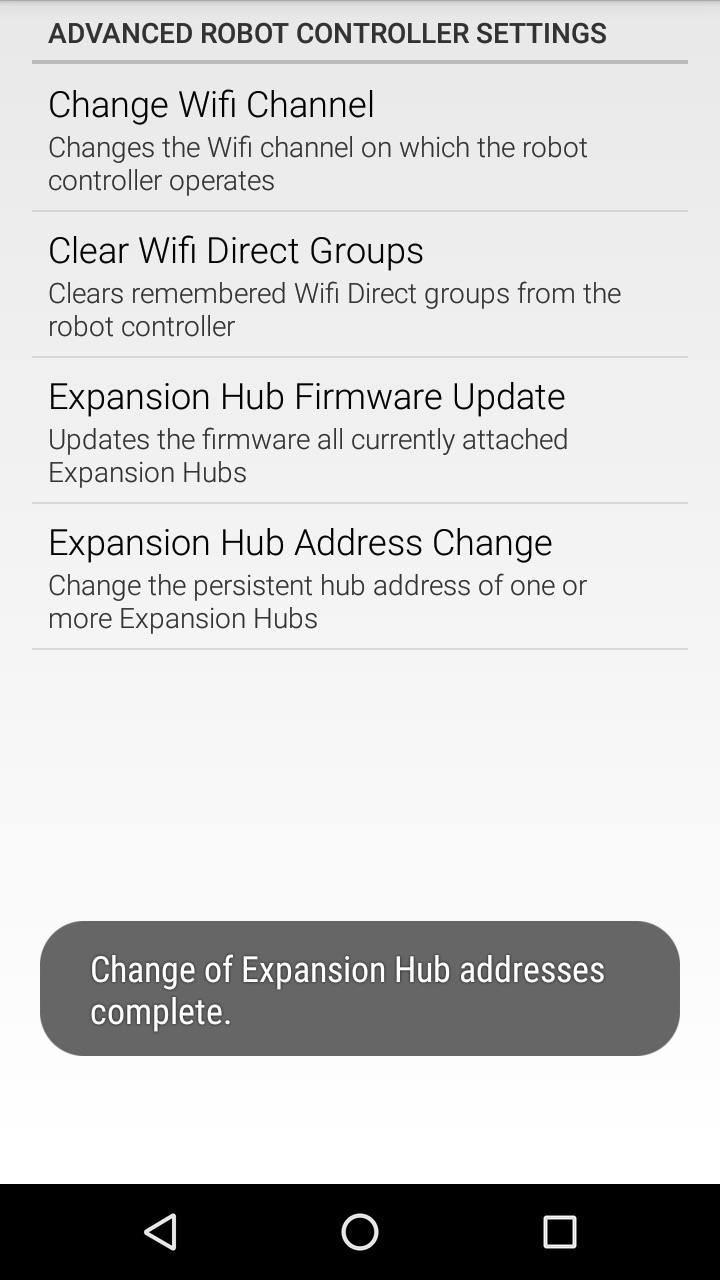
Push the “Done” button to change the address. You should see a message indicating that the Expansion Hub’s address has been changed.
Connecting the Two Expansion Hubs
5. After you have changed the address of one of the Hubs, you can use the 3-pin JST PH cable and the XT30 cable to daisy chain the two Hubs together. Before you do this, disconnect the 12V battery and power switch from the first Expansion Hub.
Use the XT30 extension cable to connect an XT30 power port on one of the Expansion Hubs to an XT30 power port on the other Hub.
6. The Expansion Hubs use the RS-485 serial bus standard to communicate between devices. You can use the 3-pin JST PH cable to connect one of the ports labeled “RS485” on one Expansion Hub to one of the ports labeled “RS485” on the other Expansion Hub.
Note that it is not important which “RS485” port that you select on an Expansion Hub. Either port should work.
7. Once you have the two devices daisy chained together (12V power and RS-485 signal) you can reconnect the battery and power switch, and then connect the Robot Controller and power on the devices.
Configuring Your Expansion Hubs
If you successfully daisy chained your two Expansion Hubs, then you should be able to create a new configuration file that includes both devices.
Note: If you already have a configuration that contains just the USB-connected Expansion Hub, you can add the second Expansion Hub by editing the configuration and pressing the “Scan” button.
Connect the Robot Controller and select the Configure Robot option from the Settings menu. Press the New button to create a new configuration file. When you first scan for hardware, your Robot Controller should detect the Expansion Hub that is immediately connected to the Robot Controller via the OTG adapter and USB cable. The Robot Controller will automatically label this device as an Expansion Hub “Portal”. The Robot Controller will communicate through this portal to the individual Expansion Hubs.
If you click on the Portal item in the configuration screen, you should see two Expansion Hubs listed, each with their respective addresses as part of their default device name.
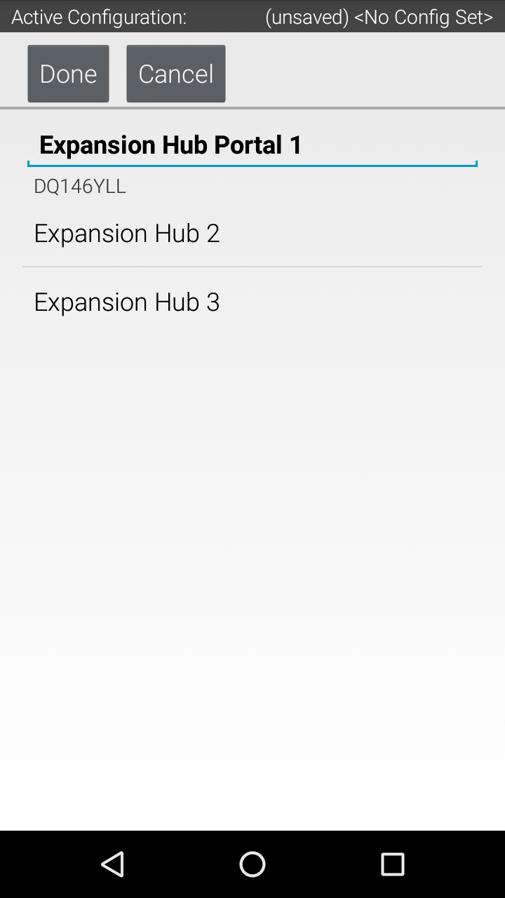
You can save this configuration file and return to the main screen of the Robot Controller. After the robot has been restarted, each Hub’s LED should be blinking in the manner that indicates its individual address.
Congratulations, you are now ready to use your dual Expansion Hubs! You can configure and operate these Hubs as you would an individual Hub.